Ш§ПхдЄгІСІЙЋТЗЛьФ§ЭССЌајСКЧХЩЯВПНсЙЙЩшМЦ(60mЃЋ100mЃЋ60m)(ШЮЮёЪщ,БЯвЕТлЮФ37000зж,CADЭМ15еХ)
еЊ вЊ
ЫцзХПЦбЇЕФШеаТдТвьЃЌЧХСКЕФЩшМЦдНРДдНЧїНќгкУРЙлОМУЁЂЪЪгУАВШЋЃЌПМТЧЕФвђЫиИќЖрСЫЁЃЕЋзїЮЊБЯвЕЩшМЦВЛПЩФмЯёЪЕМЪЩшМЦФЧбљзіЕНУцУцОуЕНЃЌдкБОЩшМЦжажївЊНтОіЫФИіЗНУцЕФЮЪЬтЃКЧХСКНиУцаЮЪНЕФФтЖЈЁЂЧХСКНсЙЙФкСІЕФМЦЫуЁЂжїСКдЄгІСІИжНюЕФбЁХфКЭНиУцбщЫуЁЃ
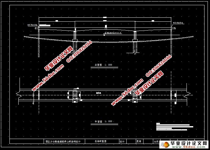
БОЩшМЦЪЧвЛИіШ§ПхдЄгІСІЙЋТЗЃЈ60m+100m+60mЃЉСЌајЧХЩЯВПНсЙЙЩшМЦЃЌЧХУцОЛПэ20mЃЌЫФГЕЕРЃЌСНБпШЫааЕРИїПэ2.25mЃЛВЩгУЯђаЮНиУцЃЌПчжаСКИп2.5mЃЌжЇзљДІСКИп6mЃЛЭЈЙ§СНИіЪЉЙЄНзЖЮЭъГЩЧХСКЕФЪЉЙЄЁЃ
ТлЮФе§ЮФАќРЈОХДѓЦЊЁЃЪзЯШЮЊаїТлЃЌНщЩмСЫгыЩшМЦгаЙиЕФвЛаЉаХЯЂЃЌвдМАСЌајСКЧХЕФжївЊЬиЕуЃЌИХЪіСЫЧХСКЕФжївЊЩшМЦКЩдиЃЛЕквЛеТНтОіСЫСКНиУцаЮЪНЕФФтЖЈЮЪЬтЃЌИљОнЧХСКНсЙЙЬиЕуФтЖЈСЫЧХСККсНиУцаЮЪНвдМАЦфдкзнЯђЕФБфЛЏЗНЪНЃЛЕкЖўеТНјааНсЙЙФкСІЕФМЦЫуЃЌМЦЫуЗНЗЈЮЊгаЯодЊЗЈЃЌЪЕМЪВйзїгІгУMIDSAЃЈЧХСКНсЙЙЗжЮіЯЕЭГЃЉНјааМЦЫуЃЛЕкШ§еТжївЊНјааСЫНиУцХфНюЃЛХфНюЭъГЩКѓЕкЫФеТНјааСЫдЄгІСІЫ№ЪЇМЦЫуЃЛЕкЮхеТНјааСЫНсЙЙДЮгІСІМЦЫуЃЛЕкСљеТЪЧНиУцбщЫуВПЗжЃЌжївЊвРОнЁЖЙЋТЗИжНюЛьФ§ЭСМАдЄгІСІЛьФ§ЭСЧХКЩшМЦЙцЗЖЁЗРДбщЫуНиУцЕФЧПЖШЃЌПМТЧСЫЛьФ§ЭСЪеЫѕЁЂаьБфДЮФкСІЕШвђЫиЕФгАЯьЃЛзюКѓЪЧжївЊЙЄГЬСПЕФМЦЫуКЭЪЉЙЄзщжЏЩшМЦЁЃ
НсЙЙЩшМЦжаЃЌШЋЧХЙВЗжЮЊ53ИіЕЅдЊЃЌВЩгУMIDAS РДМЦЫуФкСІЃЌгУExcelРДМЦЫуВПЗжБэИёЃЌВПЗжжЦЭМгУAUTOCADЃЌЪЙЙЄзїЕУЕНДѓДѓМђЛЏЁЃеХРНюВЩгУКѓеХЗЈЃЌдкЩшМЦЙ§ГЬжавЊПМТЧИїЯюдЄгІСІЫ№ЪЇКЭдЄгІСІв§Ц№ЕФЕЏадЖўДЮСІОиЁЂЮТЖШБфЛЏМАжЇзљВЛОљдШГСНЕв§Ц№ЕФДЮФкСІв§Ц№ЕФДЮФкСІЖдНсЙЙЕФгАЯьЁЃзюКѓЃЌИљОнЙцЗЖзщКЯФкСІЃЌВЂЖджївЊНиУцНјааГадиФмСІМЋЯозДЬЌКЭе§ГЃЪЙгУМЋЯозДЬЌЕФМьЫуЁЃБОЩшМЦГфЗжРћгУСЫExcelЁЂAutoCADЁЂ MIDAS етМИжжШэМўНјааИЈжњЩшМЦЃЌДѓДѓЬсИпСЫМЦЫуЫйЖШЁЃЦфжавЛВПЗжГЬађКЭБэИёЕФМЦЫуЙ§ГЬвбИНгкКѓЃЌВЂзіСЫЯргІЕФЫЕУїЁЃ
ЙиМќДЪ СЌајСКЧХЃЛЯфаЮНиУцЃЛдЄгІСІЛьФ§ЭСЃЛгаЯодЊЗжЮіЗНЗЈЃЛ
Abstract
Within the developing of Science and Technology ,bridge are required more and beautiful and safe .And the course of designing a bridge is very complex. In this thesis ,it is impossible here :deigning of the sections, computation of internal force of the bridge, pre-stressed steel bard in the structure and checking computations of the sections according to the criterion.
The project is the bridge consists of a 100-mertre center span and two side span of 60-metre each .The cross section of this bridge is a single cell boxes with depth varying from 6.0 metres to 2.5 metres. The width of the bridge is 20 metres with 4-teack roadway whose width is 15mrtres and a 2.25mrtres sidewalk on each side. The superstructure is designed to be constructed through 2 construction stages. The longitudinal pre-stressed strands are placed in the girder during cantilever stage , which is very important in keeping the bridge safe.
There are 9 chapter in the thesis. At first, the exordium, is abort some useful information related to subject , some character of continuous bridge, and the author focuses on the design of the section. And then, the first character, based on the peculiarity of the structure and former designs, the author designed the sections and their variety along the girder. Calculation of the internal force can be found in the second chapter. Finite element analysis method is used for compation. In fact, a program MIDAS is used in the process of the compation. Then, the author began to design the pre-stressed steel in the structure and check the computations of the sections according to Specifications for Design of Reinforced Concrete and Pre-stressed Concrete Highway Bridge and Culverts. In this stage, we must considering the possible effect of secondary force caused by pre-stressed , concrete creep and shrinkage, temperature variation, and support settlement. In the final chapter, the author mainly calculates the amount of the construction .
MIDAS is employed to computer the internal force ,of structure. According to the results of the MIDAS, the tabulation of the design are computed though excel. And parts of the drawing gained through AUTOCAD. Post-tensioning is adopted tendons the tendons The losses of pre-stressed forces are considered too. Finally, supporting capacity computed after internal forces are assembled according to <<Bridge Specification>>.
During this project ,I use software to aid my design, such as Excel, AUTO-CAD,MIDAS and so on .And they consumedly increased the calculation speed. The tables of Excel have been listed at the end of the thesis .
key words continuous beam bridge; box-section; pre-stressed concrete;
sinite element analysis method;
ЙЋТЗдЄгІСІЛьФ§ЭССЌајСКЧХЩЯВПНсЙЙЩшМЦ ЃЈ60mЃЋ100mЃЋ60mЃЉЃЛ
1ЁЂ ЩшМЦдЪМзЪСЯ
ЃЈ1ЃЉ жївЊММЪѕжИБъ
КЩдиВМжУЃКЦћЃГЌ20МЖЁЂЙвЃ120ЁЂШЫШККЩди3KN/ЉOЃЛ
ЧХУцПэЖШЃК0.25mРИИЫЃЋ2.25mШЫааЕРЃЋ15mГЕааЕРЃЋ2.25mШЫааЕРЃЋ0.25mРИИЫЃН20m;
ЧХУцзнЦТЃК0ЃЅЃЈЦНЦТЃЉ
ЧХУцКсЦТЃК±1.5ЃЅЃЛ
ЧХжсЦНУцЧЎаЭЃКжБЯпЁЃ
ЃЈ2ЃЉ ВФСЯЙцИё
СКЬхЛьФ§ЭСЃК50КХЛьФ§ЭСЃЛ
ЧХУцЦЬзАЃК40КХЗРЫЎЛьФ§ЭСЃЛ
РИИЫЛьФ§ЭСЃК25КХЛьФ§ЭСЃЛ
дЄгІСІИжНюМАУЊОпЃК
жїСКзнЯђдЄгІСІИжНюгУ24- 15.24ИпЧПЖШЫЩГкИжНЪЯп(1-Ёщ 15.24ЖЯУцЛ§ЮЊ137.4m ЉOЃЉ, ;ЖдгІУЊОпЮЊYM15-12ЃЛЖдгІВЈЮЦЙмОЖЮЊЁщ92mm;ЖдгІЕцАхБпГЄЮЊ`240mmЃЛУЊОпжЎМфзюаЁжааФОрЮЊ290mmЃЛУЊОпжааФгыЙЙМўБпдЕжЎМфзюаЁОрРыЮЊ185mmЁЃ
ЃЈ3ЃЉ ЕижЪЫЎЮФзЪСЯЃКМћМаНДѓЧХЪЉЙЄЭМЃЈСэИНЃЉЃЛ
ЃЈ4ЃЉ ЧХУцЦНзнЖЯУцЭМЃКМћМаНДѓЧХЪЉЙЄЭМЃЈСэИНЃЉЃЛ
ЃЈaЃЉ дкжЇМмЩЯЪЉЙЄжаМфЖеЖЅ0ЃЃЖЮЃЛ
ЃЈbЃЉ дкТњЬУжЇМмЩЯЪЉБпПчППжЇзљСКЖЮЃЛ
ЃЈcЃЉ дкжаМфЖеЖЅ0ЃЃЖЮЩЯАВжУбЁБкЙвРКЩшЪЉЃЈШЁЙвРКЩшЪЉМЏжаКЩдиЮЊ1000KNЃЉЃЛ
ЃЈdЃЉ дкжаМфЖеЖЅ0ЃЃЖЮСНВрРћгУбЁБкЙвРКж№ЖЮЖдГЦЪЉЙЄжїСКЃЛ
ЃЈeЃЉ ЪЉЙЄБпПчКЯТЃСКЖЮЃЛ
ЃЈfЃЉ ЪЉЙЄжаПчКЯТЃСКЖЮЃЛ
ЃЈgЃЉ ЦЬЩшЧХУцЦЬзАВуМАШЫааЕРАхЁЃ
ФПТМ
Ек1еТ аїТл ……...……………………………………………………………………….4
1.1 БлСКЪЉЙЄСЌајСКЧХЬиЕу……...…………...……………...……………………..….….4
1.2 ЧХСКЕФЩшМЦКЩди……...…………...………………….....……………………………6
Ек2еТ ЧХПхВМжУМАГпДчФтЖЈ……...…………...………………………...…………….…9
2.1ЧХПхВМжУЁЂНиУцаЮЪНЕФбЁдё……...…………...………………………...………….…9
2.1.1ЧХПхВМжУ……...…………...…………...………………………………………9
2.1.2 НиУцаЮЪНЕФбЁдё……...…………...………………………...………… ……..9
2.2 ЫГЧХЯђСКЕФГпДчФтЖЈ……...……………………………………………………… ….9
2.3 КсЧХЯђЕФГпДчФтЖЈ……...……………………………………………………………10
Ек3еТ жїСКФкСІМЦЫу……...…………………………………………………………….13
3.1ЕЅдЊЛЎЗжЁЂНиУцМИКЮЬиадМЦЫу …...…………………………………………………13
3.1.1 ЕЅдЊЛЎЗж……...……………………………………………………….…… .13
3.1.2 НиУцМИКЮЬиадМЦЫу…………………………………………………………..14
3.2 КудиМЦЫу……...………………………………………………………………………16
3.2.1 вЛЦкКудиМЏЖШМЦЫу……………………………………………………..……16
3.2.3 ЖўЦкКудиМЏЖШМЦЫу……………………………………… …………….……17
3.3 ЛюдиФкСІМЦЫу……...……………………………………… ……………………..….18
3.4ФкСІзщКЯМЦЫуНсЙћ……...………………………………………………….…………22
Ек4еТ дЄгІСІНюЕФМЦЫуМАВМжУ…………………………………………………….……26
4.1ХфНюЧАЯрЙижЊЪЖ……...……………………………………………………….………26
4.1.1 ИжНЪЯпМАУЊОп……...…………………………………………….…..………26
4.1.2 ИжНюМфОрМАЖдгІдЄСєЙмЕРЕФвЊЧѓ…………………… …...….….…………26
4.2 дЄгІСІНюЕФЙРЫу……...……………………………………………….………...……26
4.2.1 АДе§ГЃЪЙгУзДЬЌМЦЫу……………………………………………….….……27
4.2.2 АДГадиФмСІМЋЯоМЦЫуЪБТњзуе§НиУцЧПЖШвЊЧѓ……………………..………29
4.3 дЄгІСІНюЕФВМжУ……...……………………………………………………...….……31
Ек5еТ дЄгІСІЫ№ЪЇМЦЫу……...……………………………………………….………….32
5.1 ОЛНиУцМАЛЛЫуНиУцЕФМИКЮЬиадЫ№ЪЇ ……………………………………………….32
5.1.1 ОЛНиУц……...……………………………………………..………………….32
5.1.2 ЛЛЫуНиУц……...…………………………………………..………………….32
5.2 дЄгІСІИжНюгыЙмЕРФІВСв§Ц№ЕФгІСІЫ№ЪЇ……………………………………..…….33
5.3 гЩУЊОпБфаЮЁЂИжНюЛиЫѕКЭНгЗьбЙЫѕв§Ц№ЕФФкСІЫ№ЪЇ………………………...…….38
5.4 ЛьФ§ЭСЕФЕЏадбЙЫѕЫ№ЪЇ……...………………………………………………………39
5.5 гЩИжНюЫЩГкв§Ц№ЕФгІСІЫ№ЪЇЕФжеМЋжЕ……………………………...………………40
5.6 гЩЛьФ§ЭСЪеЫѕКЭаьБфв§Ц№ЕФдЄгІСІИжНюгІСІЫ№ЪЇ…………...……………………41
5.7 ИжНюгааЇдЄгІСІжЕМЦЫу……...……………………………………..……..…………42
Ек6еТ НсЙЙДЮФкСІМЦЫу…………………………………………..……..………………45
6.1 ЛьФ§ЭСаьБфв§Ц№ЕФДЮФкСІЕФМЦЫу…………………………………...………………45
6.1.1 НсЙЙзджиаьБфДЮФкСІ…………………………………..……………………45
6.2 дЄМгСІаьБфДЮФкСІЃЈНіПМТЧОВЖЈИжЪјЃЉ……………………………………………46
6.3 ЮТЖШв§Ц№ЕФДЮФкСІМЦЫу……...………………………………………………………46
6.4 дЄгІСІв§Ц№ЕФЖўДЮСІОи……...………………………………………………………48
6.5ЛљДЁЮЛвЦв§Ц№ЕФСЌајИеЙЙЧХДЮФкСІ…………………………………………………49
6.6 ФкСІзщКЯ……...………………………………………………...…………….………50
Ек7еТ НиУцМьЫу……...………………………………………………………………….54
7.1 АДГадиФмСІЕФМЋЯозДЬЌЕФЧПЖШМЦЫу………………………...……………………54
7.1.1 ФкСІЙцЖЈ……...……………………………………...………………………55
7.1.2 МЦЫуЪмбЙЧјИпЖШ……...………………………………...……………………56
7.1.3 МЦЫуЭфОи……...…………………………………..………………….………59
7.2 АДе§ГЃЪЙгУЕФМЋЯозДЬЌЕФЧПЖШМЦЫу…………………………..…………….………60
7.2.1 МЦЫуНиУцЛьФ§ЭСЕФЗЈЯђгІСІ…………………………….…….……………60
Ек8еТ жївЊЙЄГЬСПЕФМЦЫу……...………………………………………………….……65
8.1 жївЊЙЄГЬСП……...……………………………………………………………………65
8.1.1 C50ЛьФ§ЭСЃЈСКЬхЃЉгУСП………………………………….………………65
8.1.2 C40ЗРЫЎЛьФ§ЭСЃЈЧХУцЦЬзАЃЉгУСП……………………………….………66
8.1.3 24- 15.24ИжНЪЯпгУСП………………………………………………………66
8.1.4 УЊОпгУСП……...……………………………………………………..……….66
8.1.5 ВЈЮЦЙмгУСП……...……………………………………………...……………66
Ек9еТ ЪЉЙЄзщжЏЩшМЦ……...…………………………………………………………….67
9.1 ИХЪі……...………………………………………………………………….………. .67
9.1.1 аќБлЪЉЙЄЕФЬиЕу……...…………………………………………….……….67
9.1.2 аќБлННзЂ……...……………………………………………………….…….67
9.1.3 аќБлННзЂЪЉЙЄГЬађ……………………………………………….….………68
9.1.4 СКЖеЙЬНсДыЪЉ……...…………………………………………………...……68
9.2 ЪЉЙЄзщжЏЩшМЦИХЪі……...……………………………………………………………69
9.2.1 БржЦЪЉЙЄзщжЏЩшМЦЕФГЬађ……………………………………….….………70
9.2.2 НјааЪЉЙЄзщжЏЩшМЦашЪеМЏЕФзЪСЯ………………….……………….………70
9.2.3 БржЦЪЉЙЄзщжЏЩшМЦЕФВЮПМзЪСЯ…………………….……………….………70
9.2.4 ЗжЮізЪСЯ……...…………………………………………………..………….71
9.3 ЙЄГЬЪЉЙЄзщжЏЩшМЦ…………………………………………………………...………71
9.3.1 ЙЄГЬИХПіНщЩм……...………………………………………..……………….71
9.3.2 ЪЉЙЄЫГађМАЪЉЙЄЗНАИ………………………………………..………………72
9.3.3 бЁдёЪЉЙЄЩшБИ……...…………………………………………..…………….74
9.4 ЙЄГЬНјЖШМЦЛЎЕФБржЦ…………………………………………………...……………74
9.5 ЪЉЙЄЩшМЦ……...……………………………...……………………………………….75
9.6 жЪСПМААВШЋПижЦ……...…………………………………………...………………….76
9.6.1 ЪЉЙЄПижЦЕФФПЕФ……...………………………………………...……………76
9.6.2 жЪСППижЦДыЪЉ……...……………………………..………………………….76
9.6.3 ЪЉЙЄАВШЋДыЪЉ……...…………………………………..…………………….76
9.6.4 ММЪѕОМУжИБъ……...…………………………………..…………………….75
9.7 ЪЉЙЄзЂвтЪТЯю……...……………………………………………...………………….77
9.7.1 жїЧХЯфСК……...……………………………………..……………………….77
9.7.2 дЄгІСІЪј……...……………………………………..……………………….78
9.7.3 жЪСПМААВШЋПижЦ……...……………………………..……………………….78
жТаЛ………………………………………………………………….…………………….80
ВЮПМЮФЯз…………………………………………………………….…………………….81
|