全长90m一联三跨30m+30m+30m预应力混凝土等跨连续梁桥设计(含CAD图)(任务书,开题报告,论文说明书18000字,CAD图15张)
摘 要
本设计是根据设计任务书的要求和《公路桥规》的规定,对江阴新沟河大桥北引桥进行方案比选和设计的。连续梁桥是工程上广泛使用的一种桥型,它不但具有可靠的强度,刚度及抗裂性,而且具有行车舒适平稳,养护工作量小,设计及施工经验成熟的特点。设计一座梁桥必须从桥跨布设,尺寸拟定,钢束布置以及施工方法等方面综合考虑,还要充分考虑设计参数和环境影响。本设计是一联三跨连续梁桥,截面形式为单箱双室,纵向变截面;施工方式是悬臂(挂篮)施工整体现浇。该设计首先进行恒载、活载及次内力的计算,在此基础上进行荷载组合,绘制弯矩和剪力包络图;其次,根据频遇效应组合配置预应力钢筋,并进行预应力损失的计算;最后,对该连续梁桥进行验算,是否满足设计要求。下部结构采用钻孔灌注桩,支座采用盆式橡胶支座,并分别对桥墩和桩基础进行了计算和验算。
本设计全部设计图纸采用计算机辅助设计绘制,计算机编档、排版,打印出图及论文。并且翻译了一篇英文短文“Behaviour of one-way concrete slabs reinforced with CFRP grid reinforcements.”
关键词:设计 连续梁桥 悬臂施工(挂篮) 预应力
Design of Prestressed Concrete Equal Span Continuous Girder Bridge of North Approach Bridge of Xingou River Bridge in Jiangyin ( 3×30 m)
【Abstract】This design is based on the requirements of the design mission book and the provisions of the “Road Bridge Regulations” to compare the design and design of the north approach bridge of the Jiangyin Xingou River Bridge. The continuous girder bridge is a kind of bridge widely used in engineering. It not only has reliable strength, rigidity and crack resistance, but also has the characteristics of comfortable and stable running, small maintenance workload, mature design and construction experience. The design of a girder bridge must be comprehensively considered from the aspects of bridge layout, size planning, steel beam layout and construction methods, etc. It is also necessary to fully consider design parameters and environmental impact. The design is a three-span continuous girder bridge with a single-chamber double-chambered cross-section and a longitudinally-varying cross-section. The construction method is an integral cast-in-place construction of a cantilever (hanging basket) construction. The design firstly carries out the calculation of dead load, live load and sub-internal force. Based on this, the load combination is performed and the bending moment and shear envelope diagrams are drawn. Secondly, the prestressed steel bar is configured according to the short-term effect, and the prestressing steel is lost. Calculation; Finally, check the continuous beam bridge to meet the design requirements. The substructure uses cast-in-place bored piles, and the stand uses potted rubber bearings. It calculates and verifies the piers and pile foundations separately.
All design drawings of this design are drawn using computer-aided design, computerized documentation, typesetting, and printed drawings and papers. And he translated an English essay "Behaviour of one-way concrete slabs reinforced with CFRP grid reinforcements."
【Key Words】 design; continuous bridge; the cantilever (hanging basket); prestress
标准跨径
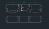
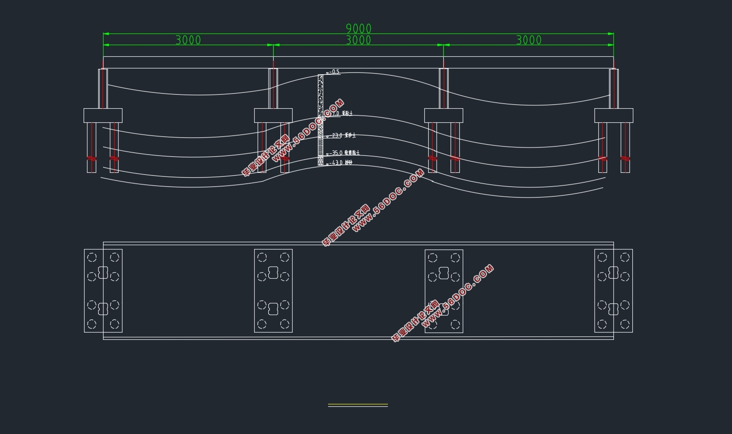
江阴新沟河大桥北引桥总长90 m。按照设计任务书中的要求,本联设计要求采用等跨等截面连续箱梁结构形式,布置时,确定本联的跨径布置如下:
30m+30m+30m =90m
目 录
摘 要 1
第一章 方案设计 1
1.1 跨径布置 1
1.2 顺桥向设计 2
1.3横桥向设计 2
第二章 恒载计算 4
2.1 节段划分及截面几何要素计算 4
2.2 一期恒载计算 5
2.3 二期恒载计算 5
2.4 总恒载计算 6
第三章 活载计算 9
3.1 汽车荷载 9
3.2 最大、最小弯矩及其对应的剪力计算 10
3.3 最大、最小剪力及其对应的弯矩 14
第四章 次内力计算 18
4.1 温度次内力计算 18
4.2 支座沉降次内力计算 22
第五章 内力组合及内力包络图 24
5.1 频遇效应组合 24
5.2 准永久组合 25
5.3 基本组合 26
5.4 包络图 27
第六章 预应力筋的计算与布置 29
6.1 原理与方法 29
6.2 预应力筋的配置 29
6.3 钢束布置 33
第七章 净截面及换算截面几何特性计算 37
7.1 概述 37
7.2 净截面几何性质计算 37
7.3 换算截面性质计算 38
第八章 预应力损失及有效预应力计算 40
8.1 控制应力及有关参数计算 40
8.2 摩擦损失 40
8.3 锚具回缩损失 41
8.4 弹性压缩损失 43
8.5应力松弛损失 45
8.6收缩徐变损失 46
8.7预应力损失组合及有效预应力计算 50
第九章 承载能力极限状态验算 51
9.1 正截面承载力验算 51
9.2 斜截面抗剪承载力验算 53
第十章 正常使用极限状态验算 56
10.1 抗裂验算 56
第十一章 持久状况和短暂状况应力验算 61
11.1 持久状况截面混凝土法向应力验算 61
11.2 短暂状态应力验算 64
第十二章 墩及桩基础设计与计算 66
12.1 支座 66
12.2 墩身设计与验算 67
12.3 桩基础设计 69
参考文献 72
致 谢 73
|