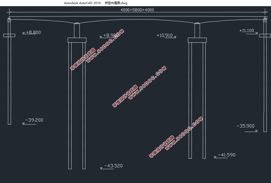
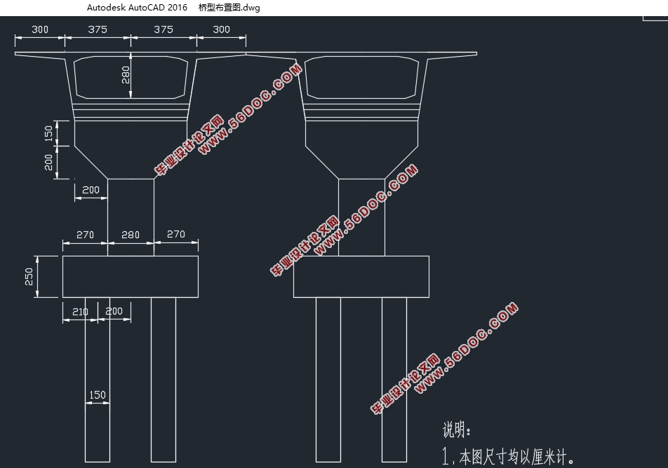
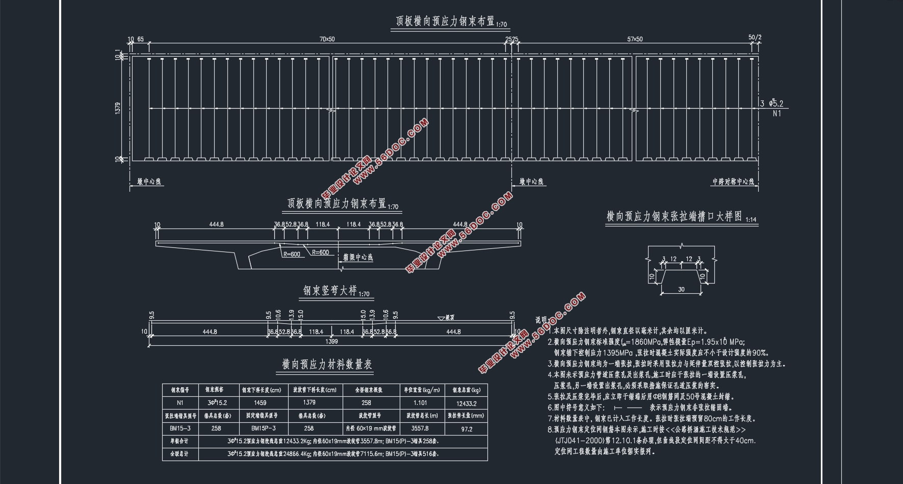
(40+58+40)m预应力混凝土变截面连续箱梁桥施工图设计(含CAD图)(任务书,开题报告,论文说明书21000字,CAD图14张)
摘要
预应力混凝土变截面连续箱梁桥不仅具有结构自重小,跨度大的特点,而且它的抗裂性能、耐久性能、刚度和外型的美观程度都要优于普通混凝土桥梁,在实际的使用情况中也能让车辆的行驶更加的舒适。以上的种种特点都让预应力混凝土梁桥在大跨度桥梁中得到广泛的应用。
本设计跨径为(40+58+40)m预应力混凝土变截面连续箱梁桥,荷载等级为公路—I级荷载,本设计的变截面形式为单箱单室,路宽28m,本设计中梁宽14m,支点处梁高3.2m,跨中截面梁高1.8m。在本设计中包括了上部结构的桥梁Midas电算和下部结构的手算,上部结构主要包括主梁和配筋计算,下部结构包含有桥墩、桥柱、钻孔灌注桩等的设计和配筋计算。要进行完整的毕业设计需要对专业知识的了解和Midas软件的灵活运用。
本次设计采用的是电算和手算相结合的方式,一方面提高了计算的精确度,另一方面也让自己参与了直接计算,能够让自己有更深的体会。
关键词:预应力、变截面连续梁桥、midas建模、满堂支架法、上部结构、下部结构。
Abstract
Prestressed concrete variable cross-section continuous box girder bridge has not only the structure of small weight, the characteristics of large span, and its crack resistance, durability, stiffness, and appearance of the beautiful degree are better than that of ordinary concrete Bridges, in the actual usage will also make the vehicle driving more comfortable. All these characteristics make the prestressed concrete bridge widely used in the bridge of large span.
This design models for (40 +58 + 40) m prestressed concrete variable cross-section continuous box girder bridge, highway - grade I load, load level for the variable cross-section form of this design is a single box single room, right 28 m, this design centre sill 14 m wide, pivot beam 3.2 m high, The cross beam height is 1.8 m. In this design, including the upper structure of bridge Midas computer and the lower structure by hand, the upper structure mainly includes the main girder and reinforcement calculation, the bottom structure contains a bridge, the bridge column, the design and reinforcement calculation of bored piles, etc. Complete graduation design requires the knowledge of expertise and the flexibility of Midas software.
This design USES a computer and a hand is a combination of, on the one hand, to improve the precision of the calculation, on the other hand also participated in the direct calculation, can let oneself have a deeper experience.
Keywords: Prestressed, cross-section continuous box girder bridge, Midas model, manchu scaffold, upper structure and lower structure.
桥式方案的选择
本桥跨径布置为40+58+40m,主梁为箱形预应力混凝土结构;设计汽车荷载:公路-Ⅰ级;设计基准期:100年。本设计的要求对桥梁的外观和桥梁的承载能力要求较高。在这样的要求下我们需要选择外型比较美观的桥型、在受力上合理、在施工方面要方便的方案。连续梁桥具有较好的经济性实用性,变截面桥型美观,在进行了多项对比之后将桥型方案确定为连续梁桥。


目 录
第一章 绪论 8
1.1地形地貌地质 8
1.2桥梁的方案设计 8
1.2.1桥式方案的选择 8
1.2.2预应力混凝土连续梁桥概述 8
1.2.3毕业设计的目的和意义 9
第二章 结构初步设计 10
2.1截面尺寸拟定 10
2.1.1变截面梁桥的尺寸形式 10
2.1.2主梁高度 10
2.1.3顶底板厚度 10
2.1.4腹板厚度 10
2.1.5承托 12
2.2施工方案 12
2.2.1施工方式 12
2.2.2施工注意事项 12
第三章 主梁内力计算 14
3.1建模过程 14
3.1.1设置单位 14
3.1.2定义材料和截面 14
3.1.3建立模型框架 15
3.1.4定义材料时间依存特性并连接 15
3.1.5输入边界条件 16
3.1.6输入荷载 16
3.1.7输入移动荷载 17
3.1.8定义施工阶段信息 18
3.2桥梁受力分析 18
3.2.1 成桥状态内力分析 18
3.2.3 活荷载效应的计算 20
3.2.4 内力组合 22
第四章 预应力钢束的估算及布置 27
4.1钢束布置 27
4.1.1钢束布置构造要求 27
4.1.2钢束布置原则 27
4.2预应力钢束的估算 28
4.3钢束起弯角和线型的确定 32
第五章 非预应力钢筋的估算与布置 35
5.1非预应力钢筋面积估算 35
5.2普通钢筋布置 36
第六章 预应力损失计算 38
6.1 预应力钢筋的输入 38
6.1.1定义添加钢束特征值 38
6.1.2 布置钢束形状 38
6.1.3定义预应力荷载工况 40
6.1.4定义施工阶段 40
6.2普通钢筋的输入 40
6.3基本理论 41
6.4预应力损失计算 41
6.4.1预应力钢筋与管道之间摩擦引起的应力损失 41
6.4.2后张法锚具变形、钢筋回缩和接缝压缩引起的应力损失 41
6.4.3后张法由混凝土弹性压缩引起的应力损失 42
6.4.4后张法由钢筋松弛引起的预应力损失终极值 43
6.4.5后张法由混凝土收缩、徐变引起的预应力损失 43
6.4.6截面预应力损失合计和有效预应力 44
6.4.7预应力损失 44
第七章 预应力与普通钢筋抗力验算 47
7.1施工阶段法向压应力验算 47
7.2受拉区钢筋的拉应力验算 49
7.3使用阶段正截面压应力验算 52
7.4使用阶段斜截面主压应力验算 53
7.5使用阶段正截面抗弯验算 55
7.6使用阶段斜截面抗剪验算 58
第八章 墩柱的设计与计算 62
8.1桥墩的尺寸 62
8.2墩帽的设计与计算 62
8.2.1墩帽自重及内力计算 62
8.2.2配筋计算 63
8.3墩柱的设计 66
8.3.1荷载计算 66
8.3.2截面配筋 67
8.3.3承载力复核 68
第九章 钻孔灌注桩和承台设计 70
9.1荷载计算 70
9.2桩长计算 70
9.3桩的内力及位移计算 72
9.4桩基础内力验算 77
9.5桩身配筋 78
9.6承台设计 79
参考文献 80
致 谢 82
|


