沙坝大桥6×40m预应力钢筋混凝土连续梁桥设计(含CAD图)(任务书,开题报告,外文翻译,论文说明书19000字,CAD图3张)
摘要
本设计为沙坝大桥的设计计算,根据桥梁具体的地质情况与相应的设计规范,确定了两个初步可行的桥梁方案并进行比较与选择,在经济、美观、耐久、合理的原则下,最终确定了桥梁为6×40m预应力钢筋混凝土连续梁桥,截面采用两个分离式单箱单室截面。
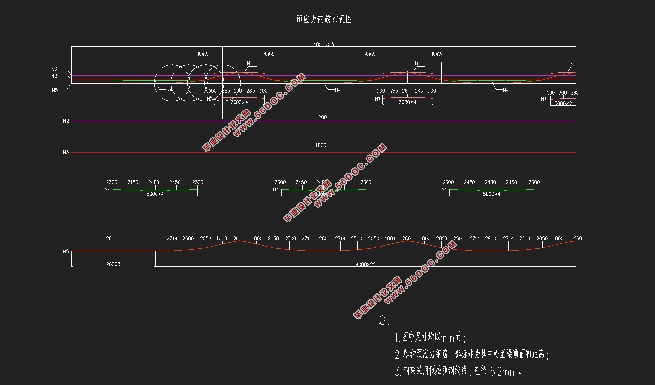
确定了桥梁方案后,通过Midas软件对拟定的桥梁进行进一步设计和计算,设计主要包括Midas模型的建立、施工阶段分析、结构内力计算等。本次设计考虑的荷载主要包括重力荷载、二期恒载、车辆荷载、温度荷载、支座位移荷载。除了上部结构的设计,我还进行了下部结构的部分计算、预应力钢束估算与布置。
本次设计共耗时2个月,通过这段时间的学习,我对桥梁设计有了更深的认识,同时也认识到学习的无止境,为以后的进一步学习工作打下了一定的基础。
关键词:预应力钢筋混凝土连续梁桥、结构内力计算、桥梁设计、荷载
Abstract
This design is the design and calculation of Sha Ba bridge.According to the specific geological conditions and corresponding design specifications of the bridge, two feasible bridge schemes are determined and compared. Under the principle of economy, beauty, durability and rationality, the bridge is made of 6 * 40m prestressed reinforced concrete continuous girder bridge, with two separate single- box- single -room sections.
After determining the bridge scheme, the bridge is further designed and calculated by Midas software. The design mainly includes the establishment of Midas model, the analysis of construction stage, and the calculation of structural internal force. The load considered in this design includes the first and two periods of load, vehicle load, temperature load and bearing displacement load. In addition to the design of the superstructure, we have also considered the design and calculation of the substructure and the estimation and layout of prestressed steel beams.
This design took 2 months, through this period of learning, I have a deeper understanding of bridge design, and also realize that learning is endless, and laid a certain foundation for further study in the future.
Key words: prestressed reinforced concrete continuous beam bridge, structural internal force calculation, bridge design, load


目录
第1章绪论 1
预应力混凝土连续箱型截面桥概述: 1
第2章水文计算 2
2.1水文资料整理 2
2.2桥孔长度确定 3
2.3桥孔布设 3
2.4桥面最低高程 3
2.4.1桥前壅水高度 和桥下壅水高度 4
2.4.2浪高 4
2.4.3波浪坡面爬高和河湾凹岸超高 5
2.4.4桥面最低高程 6
第3章 沙坝大桥方案比选 7
3.1初选方案 7
3.2比选方案一:预应力混凝土(等截面)连续梁桥 7
1、主梁上部构造 7
2、桥梁下部构造 8
3、桥梁施工方案与注意事项 8
4、受力特征 8
5、主要工程数量 9
3.3比选方案二:钢管混凝土系杆拱桥 9
1、主桥构造 10
2、施工方法 10
3、受力特征 10
4、主要工程量 11
3.4方案比较 11
第4章 桥梁结构设计与内力分析 13
4.1桥梁上部结构设计 13
4.1.1桥型布置 13
4.1.2孔径的布置 13
4.1.3桥梁横截面形式 13
4.1.4桥面布置 14
4.1.5荷载组合 14
4.2预应力钢束的估算与布置 16
4.2.1预应力钢束特性值 16
4.2.2荷载信息 16
4.2.3估索阶段结构内力分析 17
4.2.4预应力钢筋估算 24
4.2.5钢束的布置 25
4.3上部结构荷载内力分析与计算 26
4.3.1模型的建立 26
4.3.2桥梁结构单元的划分 26
4.3.3桥梁所用材料的定义 27
4.3.4桥梁截面设计 27
4.3.5边界支承条件的确定 27
4.3.6主梁内力计算分析 28
4.3.7 施工阶段正截面法向应力验算 33
4.3.8受拉区预应力钢筋拉应力验算 40
4.3.9使用阶段正截面应力验算 44
4.3.10斜截面主压应力验算 51
4.4桥梁下部结构设计与计算 58
4.4.1地质与水文资料 58
4.4.2尺寸与材料 58
4.4.3荷载情况 58
4.4.4桩长的计算 58
4.4.5桩的内力计算 59
4.4.6局部冲刷线以下深度 处桩截面的弯矩 计算 60
4.4.7桩身配筋计算及桩身材料截面强度验算 61
第5章 施工方案设计 63
5.1主要施工方法 63
5.2梁体的具体施工过程分析 63
(一)施工阶段一(CS1) 63
(二) 施工阶段二(CS2) 64
(三) 施工阶段三(CS3) 64
(四) 施工阶段四(CS4) 64
(五) 施工阶段五(CS5) 65
(六) 施工阶段六(CS6) 65
(七) 施工阶段七(CS7) 66
致谢 67
参考文献: 68
|


