5×20m预应力混凝土箱梁桥施工图设计(含CAD图)(任务书,开题报告,外文翻译,论文说明书12000字,CAD图26张)
摘 要
梁,不同跨的主梁横向连接较弱。简支梁是静定结构,相邻各跨单独受力,受力图示明确,比较容易建立计算模型,而且结构受力比较单纯,不受支座变位等影响,在温度左右下, 用得比较广泛。
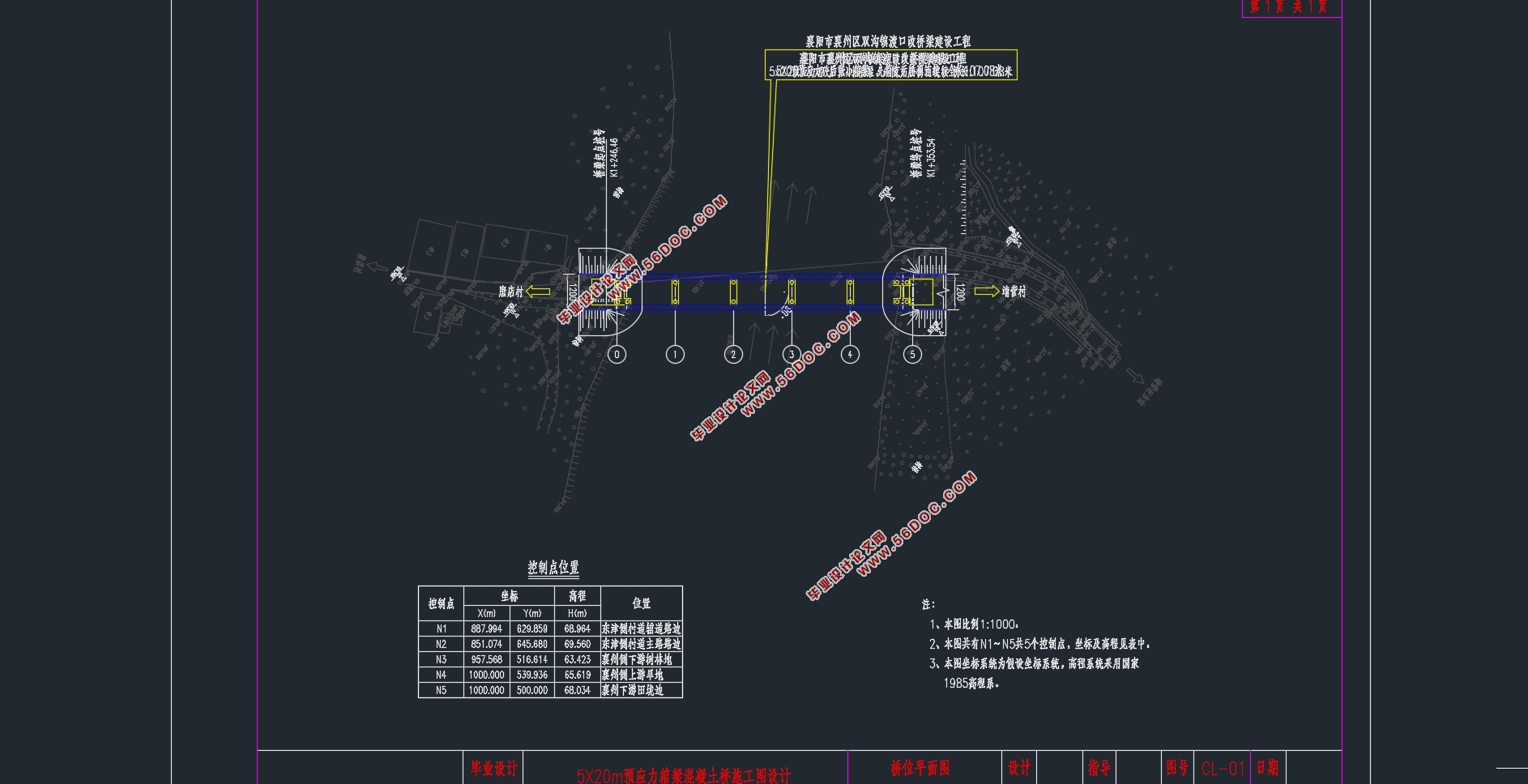
本次毕业设计就选用了预应力混凝土装配式小箱梁。桥梁全长100m,桥跨布置为5×20m的五跨预应力箱梁桥。设计荷载为公路-I级荷载。
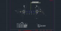
本次毕业设计以襄阳市襄州去双沟镇渡口改桥梁建设工程为背景,对其进行设计总体说明、上部结构计算、下部结构计算及主要的施工图设计。本桥梁是跨径布置为5×20m的预应力混凝箱梁桥,桥宽12m。本次设计过程主要为:总体布置、尺寸拟定、利用 进 算、 、挠度验算。而桥墩桥台和桥面板的内力计算则采用手算。
关键词:预应力混凝土简支梁桥;箱梁桥;MIDAS建模;上部结构;下部结构
Abstract
The superstructure of the simply-supported girder bridge consists of a main bearing beam that is simply supported on the abutment at both ends. The simply-supported beam is a statically determinate structure. The adjacent spans are subjected to individual forces, and the structural forces are relatively simple. They are not affected by bearing displacement, etc., and are applicable to various geological conditions. The structure is also relatively simple, and it is easily standardized and assembled. Components, manufacturing and installation are more convenient, and they are the most widely used beam bridges.
For this graduation project, prestressed concrete assembled box beams were selected. The bridge has a total length of 100m and the bridge span is arranged as a 5x20m five-span prestressed box girder bridge. The design load is a road-I load.
The graduation design of this graduation project is based on the construction of the bridge construction project at the Dukou Township in Suizhou, Fuyang City. The overall description of the design, the calculation of the superstructure, the calculation of the substructure and the design of the main construction drawings are carried out. The bridge is a prestressed concrete box girder bridge with a span of 5 × 20m and a bridge width of 12m. The design process mainly includes: overall layout, dimensioning, MIDAS modeling, superstructure calculation, substructure calculation, and construction drawing. The design uses MIDAS bridge modeling software to estimate the superstructure prestressed steel bundles, and to perform layout and load limit state checking, check the limit state of normal use, check the component stress under permanent state and transient conditions, and check the deflection. . The calculation of the internal force of the lower structure and the traffic lane uses hand calculations.
After review, the bridge structure designed for graduation this time is safe and reasonable, and meets the requirements of the current regulations.
Key Words:Prestressed concrete box girder bridge;MIDAS modeling ;superstructure substructure
本次毕业设计(论文)以襄阳市襄州去双沟镇渡口改桥梁建设工程为背景,对其进行设计总体说明、上部结构计算、下部结构计算及主要的施工图设计。本桥梁是跨径布置为5×20m的预应力混凝箱梁桥,桥宽12m,双向二车道。采用MIDAS CIVIL8.35进行桥梁建模,这样不仅提高了效率,而且准确性也得到了保证。做好本次毕业设计(论文)可以使学生所学的基础理论知识与专业知识更加系统、巩固、延伸和拓展,提高学生调查研究、 分析、解决工程实际问题的能力。
技术标准
1、公路等级:二级;
2、汽车荷载等级:公路-Ⅰ级;
3、横向布置:1.5m(人行道)+9.0m(行车道)+1.5m(人行道)1;
4、桥面横坡1:双向2%;
5、设计洪水频率:1/100;
6、设计速度:60km/h。

目 录
摘 要 1
目 录 2
第1章 绪论 6
1.1预应力混凝土箱梁桥概述 6
1.2选题设计思想及意义 7
第2章 设计基础资料及设计说明 8
2.1 桥址处自然概况 8
2.1.1 地理位置、地形地貌 8
2.1.2 工程地质条件 8
2.1.3 水文的地质的条件 9
2.1.4 气候条件 9
2.2设计说明 9
2.2.1设计依据 9
2.2.2技术标准 9
第3章 桥型方案比选 10
3.1桥梁设计原则 10
3.1.1安全性与适用性 10
3.1.2经济性和美观性 10
3.2桥梁方案比选 10
3.2.1 第一方案:装配式预应力混凝土简支箱梁桥 10
3.2.2 第二方案:连续梁刚构桥 11
3.2.3 第三方案:等截面连续梁桥 11
3.2.4 方案比选 12
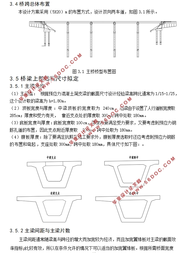
3.4桥跨总体布置 13
3.5桥梁上部结构尺寸拟定 13
3.5.1主梁高度 13
3.5.2主梁间距与主梁片数 13
第4章 上部结构信息模型建立 15
4.1 MIDAS/CIVIL建模概述 15
4.2 MIDAS/CIVIL建模 15
4.2.1设定操作环境 15
4.2.2定义材料 15
4.2.3定义截面 16
4.2.4定义变截面/变截面组 17
4.2.5建立节点 19
4.2.6建立单元 19
4.2.7定义时间依存性材料 20
4.2.8定义变界条件及边界组 20
4.2.9建立静力荷载工况 20
4.2.10建立移动荷载工况 22
4.2.11施加预应力荷载 23
4.2.12定义荷载组 25
4.2.13划分施工阶段 25
第5章 桥面板的计算 26
5.1主梁桥面板按单向板计算 26
5.1.1恒载内力取向取1m的板条计算 26
5.1.2活载内力 26
5.2主梁桥面板悬臂板的计算 27
5.2.1恒载内力以纵向取1m的板条计算 27
5.2.2活载产生的内力 28
5.2.3行车道板的设计内力 28
5.3桥面板配筋 28
5.3.1桥面板配筋 28
5.3.2抗剪验算 28
5.1.2活载内力 29
5.2主梁桥面板悬臂板的计算 30
5.2.1恒载内力以纵向取1m的板条计算 30
5.2.2活载产生的内力 30
5.2.3行车道板的设计内力值 31
5.3主梁桥面板悬臂板的计算 31
5.3.1支点处配筋,沿纵向取1m宽板条计算 31
5.3.2 跨中处的配筋,沿纵向取11m宽板条来计算 31
5.3.3抗剪验算 32
第6章 内力计算荷载组合 33
6.1恒载内力计算 33
6.2活载内力计算 36
6.3 内力组合 40
6.3.1承载能力极限状态 40
6.3.2正常使用极限状态的内力组合 42
第7章 预应力钢束数量及损失计算 45
7.1预应力钢束数量的确定 45
7.2预应力束的布置 47
7.2.1布置原则 48
7.2.2钢束的布置 48
7.3预应力损失 48
7.3.1预应力钢筋与管道壁之间的摩擦 48
7.3.2锚具变形、钢筋回缩和接缝压缩 48
7.3.3预应力钢筋与台座之间的温差 49
7.3.4混凝土的弹性压缩 49
7.3.5预应力钢筋的应力松驰 49
7.3.6 预应力损失计算的结果 49
第8章 主梁验算 54
8.1承载能力极限状态截面验算 54
8.1.1主梁截面承载能力与应力验算 54
8.1.2斜截面抗剪验算 55
8.2正常使用极限状态截面验算 55
8.2.1使用阶段正截面抗裂验算 55
8.2.2使用阶段斜截面抗裂验算 56
8.3持久状况和短暂状况构件的应力验算 57
8.3.1使用阶段正截面压应力验算 57
8.3.2使用阶段斜截面主压应力验算 58
8.3.3施工阶段正截面法向应力验算 59
8.3.4受拉区钢筋的拉应力验算 61
8.4挠度验算 61
8.5梁端锚固区的局部承压验算 62
8.6.1局部承压尺寸要求 62
8.6.2局部承压承载力验算 63
第9章 下部结构计算 65
9.1桥墩计算 65
9.1.1荷载计算 65
9.1.2截面配筋验算 66
9.2桥墩钻孔灌注桩计算 67
9.2.1荷载计算 67
9.2.2桩长计算 67
9.3桩的内力及位移计算 68
9.3.1基本假定 68
9.3.2桩的计算宽度 68
9.3.3桩的变形系数 68
9.3.4桩顶纵向水平位移验算 70
9.3.5桩截面承载力验算 71
参考文献 72
致谢 73
|