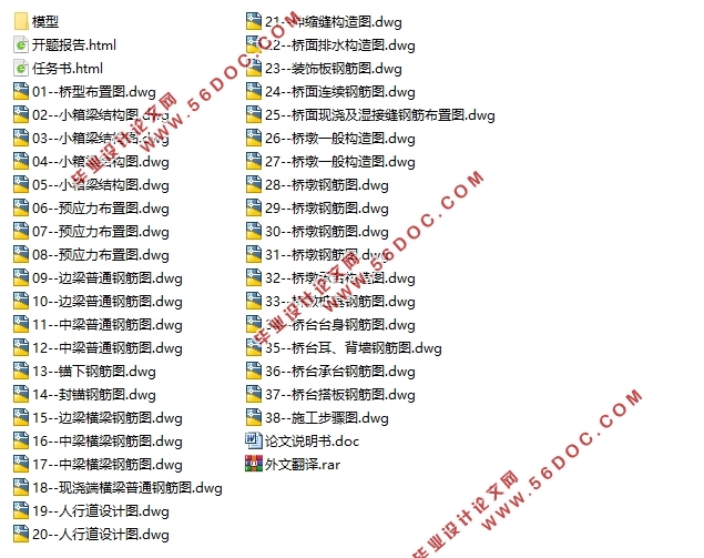
3×30m跨径布置预应力混凝土箱梁桥施工图设计(含CAD图)(任务书,开题报告,外文翻译,论文说明书21000字,CAD图38张)
摘要
此次的毕业设计题目为3×30m预应力混凝土箱梁桥施工图设计,是以柴泊湖大桥的第二联为设计背景,分别进行上、下部结构的施工图设计及检验。预应力混凝土小箱梁简支桥的优点:抗扭能力强,便于现浇施工,自重轻。一般用于跨径小于30m的城市桥梁。因为本桥是简支桥梁,不需进行各种次内力的计算。
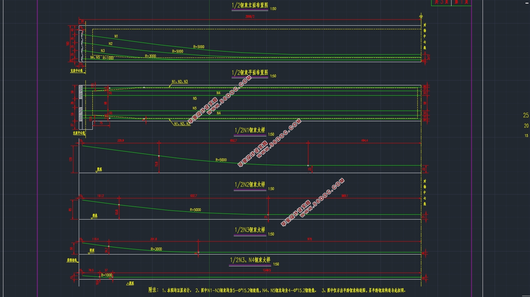
此次桥梁设计开始应该根据桥梁和道路规范,确定桥梁的截面尺寸,钢筋的用量,然后进行下部结构的设计,根据长江的地质情况,按摩擦桩进行地基承载力的设计。本次设计选用“一”字形桥台,桥墩确定为拱形框架墩,桩的类型为摩擦桩。施工方式确定为预制吊装施工法。细部尺寸确定后,使用迈达斯软件建立A类中梁和边梁的模型。导入截面尺寸,确定自重、二期、预应力荷载。通过正截面、斜截面的抗弯、抗剪承载情况来确定模型的正确,在模型通过后,就可以进行下部结构的计算了,同时也可以画CAD图了。
经过此次设计,桥梁的设计满足JTG D60—2015规范,设计通过。
关键词:简支桥梁;设计及计算;迈达斯
Abstract
The graduation project is designed for the construction drawing of 3 x 30m prestressed concrete box girder bridge. The design and inspection of the construction drawings of the upper and lower structures are carried out on the basis of the second combination of the Chai Hu bridge. The advantages of prestressed concrete small box girder simply supported bridge are: strong torsion resistance, convenient for cast-in-place construction and light weight. It is generally used for urban bridges with a span of less than 30m. Because this bridge is simply supported, it does not need to carry out the calculation of various internal forces.
The bridge design should begin with the bridge and road specifications, determine the section size of the bridge, the amount of steel, and then carry out the design of the substructure. According to the geological conditions of the Yangtze River, the bearing capacity of the foundation is designed by massage. In this design, the "one" shaped abutment is chosen, and the pier is determined as the arch frame pier, and the type of the pile is friction pile. The construction method is determined as prefabricated hoisting construction method. After determining the detail size, Midas software is used to establish the model of the middle beam and side beam. The size of the inlet section is determined, and the dead weight, the two stage and the prestress load are determined. The correctness of the model is determined by the bending and shear resistance of the cross section and the oblique section. After the model is passed, the substructure can be calculated and the CAD diagram can be drawn.
After this design, the design of the bridge satisfies the specification of JTG D60 - 2015, and the design is approved.
Key words: simply supported bridges;design and calculation;MIDAS;
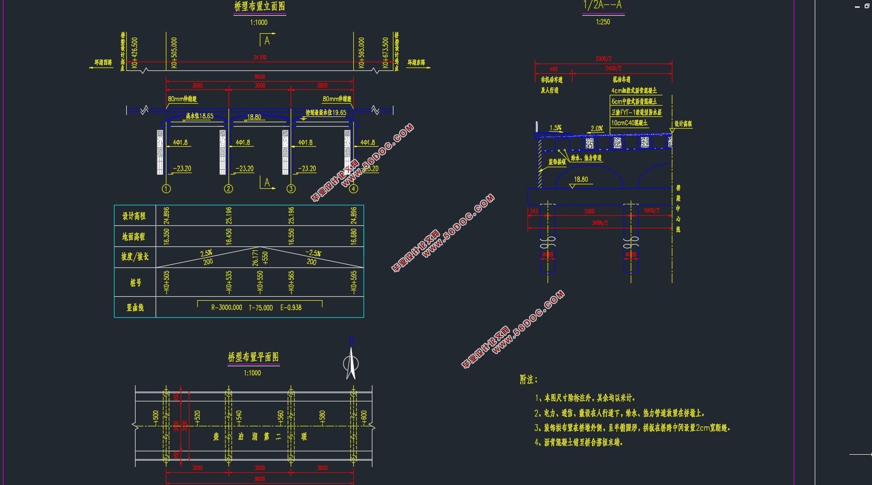
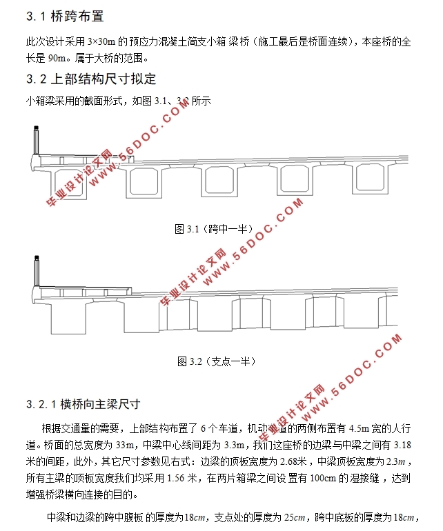
此次毕业设计以武汉市阳逻柴泊湖第二联为设计背景,对第二联采取施工图设计,根据桥梁和道路规范,确定桥梁的截面尺寸,钢筋的用量,然后进行下部结构的设计,根据长江的地质情况,按摩擦桩进行地基承载力的设计。采用3×30m的跨径布置,4.5米人行 +24米机动车道+4.5米人行 =33m(桥面全宽),一共10片梁,其中包括8片中梁和两片边梁,中梁又分为A类中梁和B类中梁。中梁的顶板宽度为2.3m,边梁的顶板宽度为2.18m,通过100cm的湿接缝把各片箱梁连接起来,最终两片梁的间距为3.3m,简支梁桥是静定结构,本来的计算量较小,但老师要求利用迈达斯建模软件,为了以后的工作,此次设计采取了建模的方式,丢弃了以往手算的惯例。既节约了时间,又学到了软件建模。
目录
第1章 绪论....................................................................................................................................1
1.1预应力混凝土简支梁桥的发展概述................................................................................1
1.2选题设计思想及意义........................................................................................................1
第2章 桥型方案比选....................................................................................................................2
2.1构思宗旨............................................................................................................................2
2.2比选原则............................................................................................................................2
2.3设计方案............................................................................................................................2
2.3.1预应力混凝土先简支后结构连续小箱梁桥.........................................................2
2.3.2预应力混凝土先简支后桥面连续小箱梁桥.........................................................3
2.3.3预应力混凝土先简支后桥面连续T梁桥.............................................................4
第3章 桥跨总体布置及结构尺寸拟定........................................................................................6
3.1桥跨布置............................................................................................................................6
3.2上部结构尺寸拟定............................................................................................................6
3.2.1横桥向主梁尺寸拟定.............................................................................................6
3.3下部结构尺寸拟定............................................................................................................7
3.3.1墩身尺寸拟定..........................................................................................................7
3.3.2桥台拟定..................................................................................................................7
3.3.3桩基础尺寸拟定......................................................................................................7
第4章 建模....................................................................................................................................9
4.1模型简化............................................................................................................................9
4.1.1横向分布系数的计算.............................................................................................9
4.1.2模型简化...............................................................................................................10
4.2主要参数说明..................................................................................................................11
4.2.1材料参数..............................................................................................................11
4.2.2荷载参数..............................................................................................................12
4.2.3边界说明..............................................................................................................13
4.3施工阶段说明.................................................................................................................13
第5章 桥梁结构内力计算.........................................................................................................14
5.1恒载内力.........................................................................................................................14
5.2活载内力.........................................................................................................................18
第6章 预应力钢筋设计及预应力损失计算.............................................................................22
6.1预应力钢筋设计.............................................................................................................22
6.1.1纵向预应力筋估算..............................................................................................22
6.1.2预应力筋的布置..................................................................................................30
6.2预应力损失.....................................................................................................................31
6.2.1 预应力钢筋与管道壁之间的摩擦.....................................................................32
6.2.2 锚具变形、钢筋回缩和接缝压缩.....................................................................32
6.2.3 预应力钢筋与台座之间的温差(本工程不考虑).........................................33
6.2.4 混凝土的弹性压缩………………………………………………………….....33
6.2.5 预应力刚筋的应力松弛…………………………………………………….....33
6.2.6 混凝土的收缩徐变………………………………………………………….....33
6.2.7 预应力损失计算结果.........................................................................................34
第7章 主要截面验算.................................................................................................................38
7.1承载能力极限状态截面验算.........................................................................................38
7.1.1正截面抗弯验算..................................................................................................38
7.1.2斜截面抗剪验算..................................................................................................43
7.2正常使用极限状态截面验算.........................................................................................44
7.2.1使用阶段正截面抗裂验算..................................................................................44
7.2.2使用阶段斜截面抗裂验算………………………………………………….…..49
7.2.3挠度验算………………………………………………………………………...52
7.3持久状况和短暂状况构件的应力验算………………………………………………..52
7.3.1使用阶段正截面压应力验算…………………………………………………...52
7.3.2使用阶段斜截面主压应力验算………………………………………………...55
7.3.3施工阶段正截面法向应力验算………………………………………………...57
7.3.4受拉区钢筋的拉应力验算……………………………………………………...61
第8章 锚下局部承压验算……………………………………………………………………..63
8.1局部受压区尺寸要求…………………………………………………………………..63
8.2局部抗压承载力计算…………………………………………………………………..63
第9章 行车道板计算…………………………………………………………………………..65
9.1中间单向板计算………………………………………………………………………..65
9.1.1横载内力………………………………………………………………………...65
9.1.2活载内力………………………………………………………………………...65
9.1.3内力组合………………………………………………………………………...67
9.2外边梁悬臂板内力计算..................................................................................................67
9.2.1横载内力...............................................................................................................67
9.2.2活载内力...............................................................................................................68
9.2.3内力组合...............................................................................................................68
9.3配筋设计………………………………………………………………………………..69
9.3.1支点处配筋……………………………………………………………………...69
9.3.2跨中配筋………………………………………………………………………...69
第10章 桥墩计算 ……………………………………………………………………………71
10.1荷载计算 ……………………………………………………………………………..71
10.2截面配筋计算 ………………………………………………………………………..71
10.3墩柱截面承载力验算 ………………………………………………………………..73
第11章 桥墩钻孔灌注桩计算 ………………………………………………………………..74
11.1荷载计算 ……………………………………………………………………………..74
11.2桩长计算……………………………………………………………………………....74
11.3桩的内力及位移计算………………………………………………………………....76
11.3.1基本假定…………………………………………………………………….....76
11.3.2桩的计算宽度……………………………………………………………….....76
11.3.3桩的变形系数……………………………………………………………….....76
11.3.4计算最大冲刷线处桩身弯矩,水平力及轴向力………………………….....77
11.3.5桩身最大弯矩位置及弯矩计算…………………………………………….....77
11.3.6计算最大冲刷线以下深度处桩截面上的弯矩及水平压应力…………….....77
11.3.7桩顶纵向水平位移验算…………………………………………………….....77
11.4桩身截面配筋计算…………………………………………………………………....78
11.5墩柱截面承载力验算………………………………………………………………....79
阅读参考文献 80
致谢 81
|
