三跨(45+70+45m)预应力混凝土变截面连续箱梁桥施工图设计(含CAD图)(任务书,开题报告,外文翻译,论文计算书25000字,CAD图纸6张)
摘要
本次我的毕业设计的设计对象是位于武汉市的府河大桥的第三联预应力混凝土变截面连续箱梁桥。我此次的设计任务是根据相关通用规范的规定计算本连续箱梁桥的上部结构,同时还要完成下部结构的计算并且设计绘制此箱梁桥的施工图。
第一步,按照公路桥规的相关规范初步确定出桥梁主梁的主要构造以及相关细部尺寸,确定支点处和跨中处的梁高,确定桥宽、顶板厚度,确定底板下缘以及上缘的变化曲线的方程,确定腹板厚度变化的形式。
第二步,利用 MIDAS CICIL 软件建立桥梁模型。首先根据之前确定的结构尺寸建立几何模型,之后添加预应力钢束和荷载,再划分施工阶段。这个过程中最重要的步骤是关于预应力束的添加,需要进行反复的调整才能找到能满足规范要求的预应力束的数量以及形状。调试完成后就可以运行分析,查看各类荷载组合下的内力图和应力图,同时在PSC界面查看模型是否满足各阶段法向压应力验算、钢筋拉应力验算、正截面和斜截面抗裂验算以及正截面抗弯验算等。
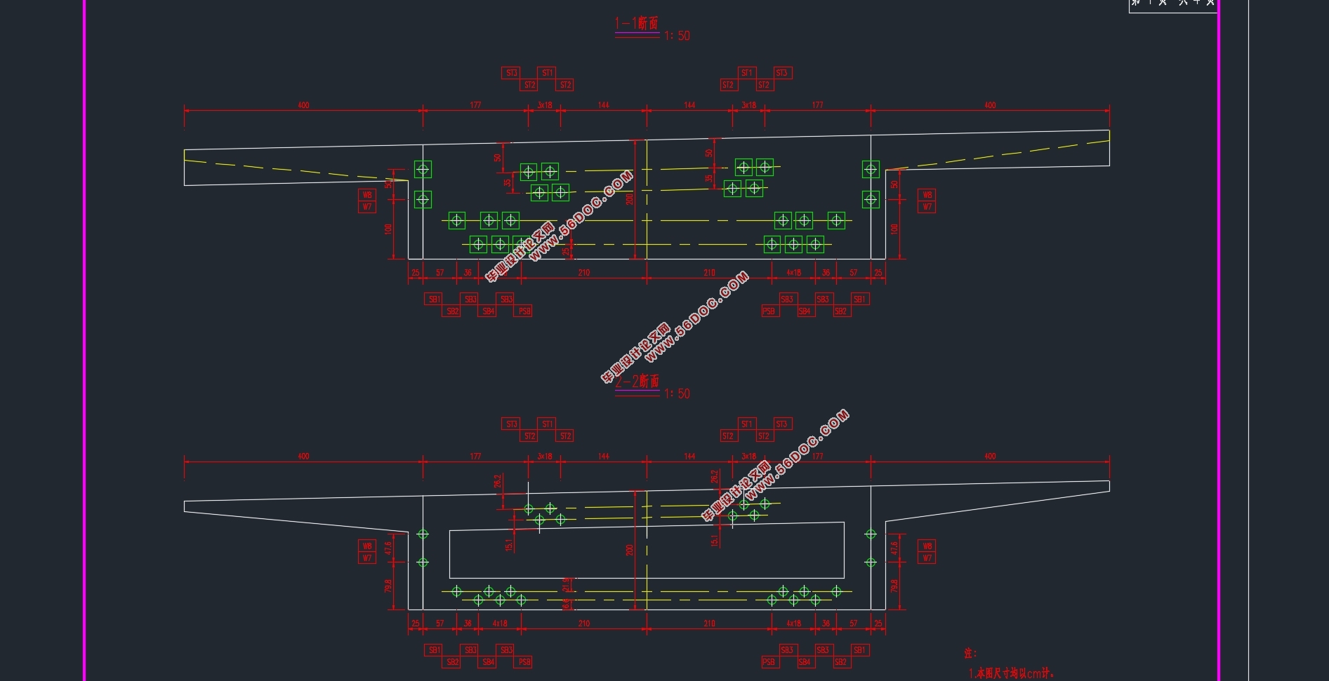
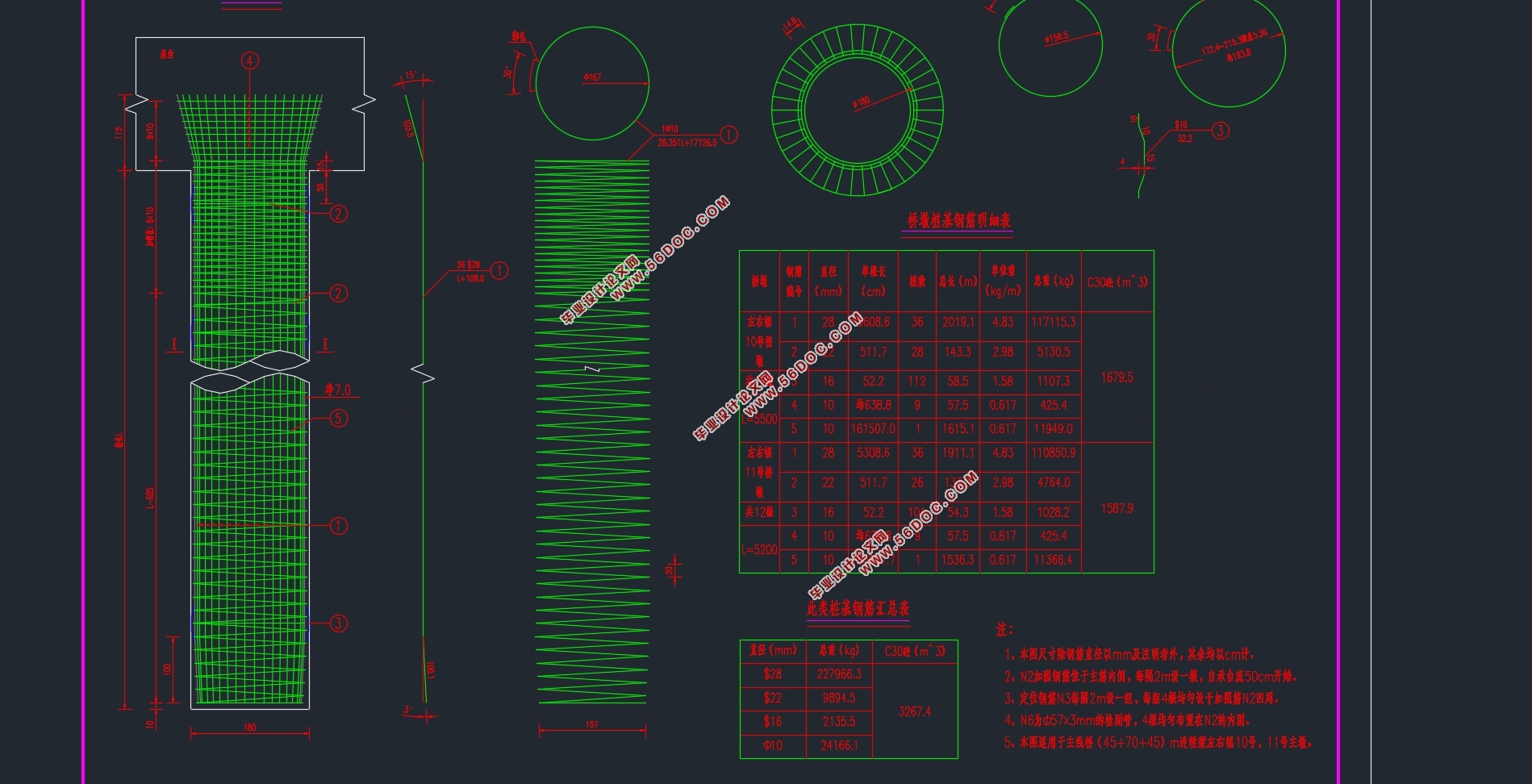
第三步,手算桥梁行车道板的承载能力和预应力钢束锚固区齿板的局部承压能力,对主墩和主墩的灌注桩进行计算和验算,绘制完成此箱梁桥的施工图。
总结:经过模型的分析和手算部分的分析验算表明,本次设计的上部、下部结构计算方法正确,持久状况承载能力极限状态强度满足规范要求,计算过程以及完成的工作数量符合设计任务书的要求。
关键词:箱梁桥;预应力混凝土;MIDAS CIVIL建模;设计计算;验算
Abstract
The object of my graduation project is the third prestressed concrete continuous box girder bridge with variable cross section in Fu River Bridge in Wuhan. My design task is to calculate the superstructure of the continuous box girder bridge according to the relevant General specification, and also to complete the calculation of the substructure and to design the construction drawing of the box girder bridge.
The first step is to determine the main structure of the bridge main beam and the related details according to the relevant specifications of the highway bridge rules, determine the beam height of the pivot point and the middle span, determine the width of the bridge and the thickness of the roof, determine the equation of the change curve of the bottom edge and the upper edge of the bottom plate, and determine the form of the change of the thickness of the web.
The second step is to build bridge model by using MIDAS CICIL software. First, the geometric model is established according to the size of the pre-determined structure, then the prestressed steel beams and loads are added, and then the construction stage is divided. The most important step in this process is the addition of the prestressed beam, which requires repeated adjustments to find the number and shape of the prestressed beam that meets the requirements of the specification. After the completion of the debugging, we can run the analysis and check the internal force diagram and the stress diagram under various load combinations. At the same time, the PSC interface can see whether the model satisfies the normal pressure stress checking, the tensile stress checking calculation, the checking calculation of the cross section and the oblique section, and the checking calculation of the normal section.
The third step is to calculate the load-bearing capacity of the bridge deck and the local bearing capacity of the prestressed steel beam anchorage zone, and to calculate and check the cast-in-place pile of the main pier and the main pier, and draw the construction drawings of the bridge.
Summary: through the analysis of the model and the analysis and calculation of the hand calculation, the calculation method of the upper and lower structure of this design is correct. The ultimate state strength of the endurance state bearing capacity is satisfied with the standard requirements. The calculation process and the amount of work completed are in accordance with the requirements of the design task book.
Keywords: girder bridge; Prestressed concrete; MIDAS CIVIL; Design and calculate ; Checking computation
1.1 工程概况
1.1.1 工程介绍
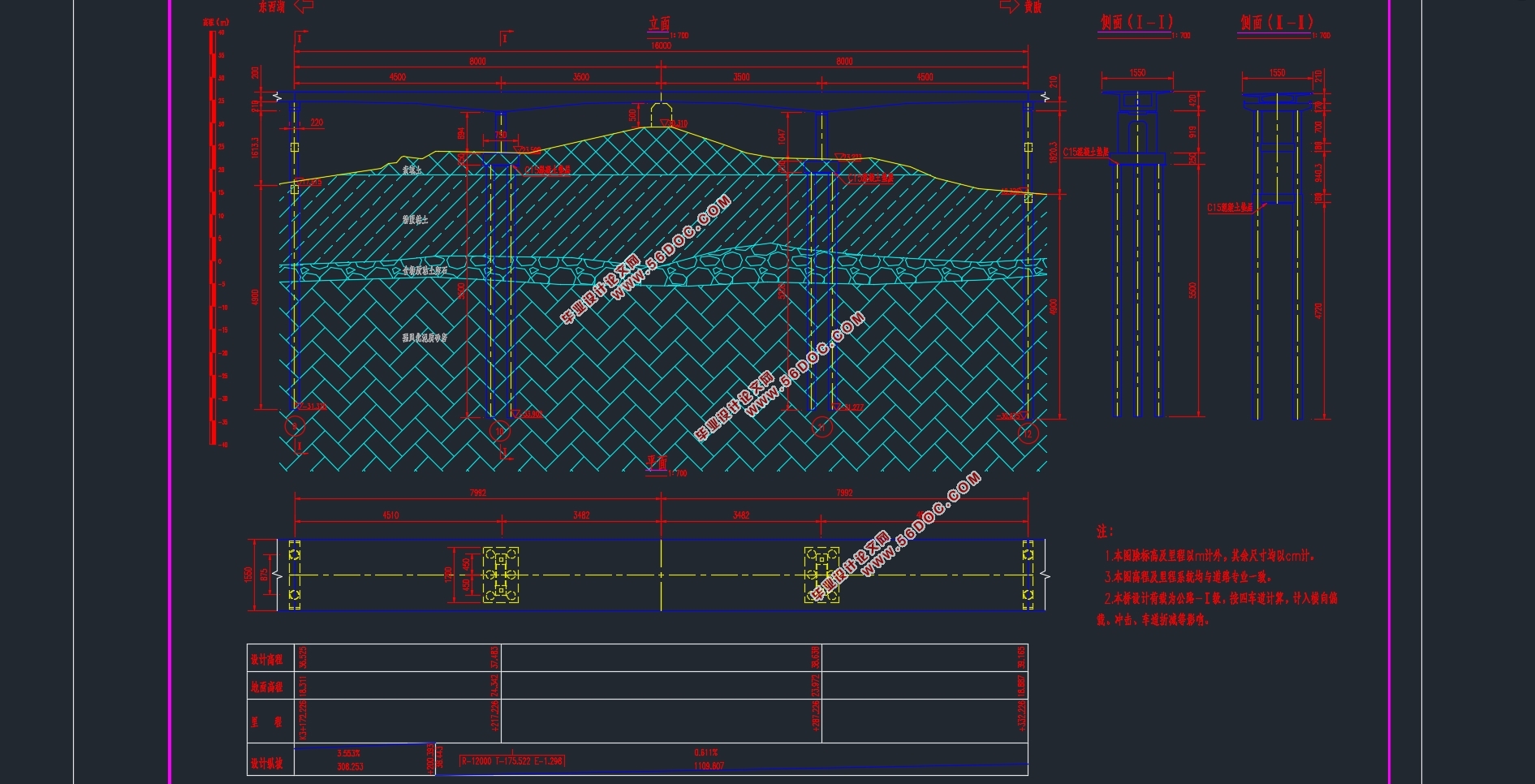
本桥位于武汉市,连接东西湖和黄陂,为府河大桥的第三联,属于副主桥。本段起点为 K3+172.226,终点为 K3+332.226;桥梁跨径布置为 ,桥梁纵向坡度为2%,双向四车道。 ,下部结构采用双柱式
。
1.1.2 地形地貌
勘察区地貌单元为河湖冲积平原,主要由第四系全新统~上、中更新统河流补湖积、冲积、冲洪积形成。线路两端地形呈波状起伏,池势总体为平缓,构成长红的Ⅰ、Ⅲ级阶地,阶地间陡坎不明显,主要呈缓坡过渡,高程在16.7~24.15m,相对高差2.0~6.0m,主要是由 组成,显环带状及鸡窝状发育有全新统湖积成因的淤泥、淤泥质土。
1.1.3 地质
地层岩性
在本阶段勒探控制深度范围内,拟建桥梁沿线地层按时代及成因,共划分为9大类,自上而下具体为:素填土(Qal),耕植士(Qpd),第四系全新统湖积成因淤泥质粘性土 四系下更新统冲积(Q1al) 粘性土及砂、砾石层及碎石土, 粉砂岩,石炭系中统 (C2)白云岩夹灰岩,志留系坟头组(S2f) 粉砂质泥岩。
1.2 设计资料及基本数据
1.2.1 技术标准
1) 荷载等级:公路-I 级。
2) 桥梁宽度:15.5m。
3) 环境类别:I类。
4) 安全等级:1 级。
5) 地震烈度:地震动峰值加速度为 , 。抗震设防烈度为 7 度。
6) 高程系统:1986年国家高程基准。
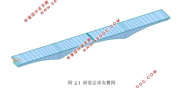
本次的方案采用全长为160m,设计主跨70m的三跨预应力混凝土连续箱梁桥。
目录
第1章 概述 1
1.1 工程概况 1
1.1.1 工程介绍 1
1.1.2 地形地貌 1
1.1.3 地质 1
1.2 设计资料及基本数据 1
1.2.1 技术标准 1
1.2.2 材料及其设计参数 2
第2章 桥跨总体布置及结构主要尺寸拟定 4
2.1尺寸拟定 4
2.1.1桥型布置 4
2.1.2 主梁结构尺寸 4
2.1.3 桥面铺装 6
2.2建立计算模型 6
2.2.1 全桥结构单元划分 6
2.2.2 全桥施工分段划分 7
2.2.3荷载信息 8
第3章 行车道板计算 11
3.1主梁桥面板按单向板计算 11
3.1.1恒载内力以纵向取1m的板条计算 11
3.1.2活载内力 11
3.2主梁桥面板悬臂板的计算 14
3.2.1恒载内力以纵向取1m的板条计算 14
3.2.2活载产生的内力 14
3.2.3行车道板的设计内力 15
3.3主梁桥面板悬臂板的计算 15
3.3.1.支点处配筋,沿纵向取1m宽板条计算 15
3.3.2跨中处配筋,沿纵向取1m宽板条计算 16
3.3.3抗剪验算 16
第4章 主梁内力计算与组合 17
4.1 恒载内力的计算 17
4.2活载内力计算 18
4.2.1横向分布系数的计算 19
4.2.2活载内力的计算 19
4.2.3计算结果 19
4.3次内力计算 22
4.3.1温度引起的内力计算 22
4.3.2支座位移引起的内力计算 23
4.3.3徐变引起的内力计算 24
4.3.4预加力产生的次内力 25
4.4承载能力极限状态的内力组合 26
4.5正常使用极限状态的内力组合 27
4.6内力组合 28
第5章 预应力钢束数量及损失计算 32
5.1预应力钢束数量的确定 32
5.2预应力束的布置 34
5.2.1布置原则 34
5.2.2钢束的布置 35
5.3预应力钢束与管道壁之间的摩擦 35
5.4锚具变形、钢束回缩和接缝压缩 36
5.5混凝土弹性压缩 36
5.6预应力钢束的应力松弛 36
5.7混凝土的收缩徐变 36
5.8预应力钢束的有效应力计算 37
第6章 主梁验算 39
6.1持久状况承载能力极限状态验算 40
6.1.1截面受压区高度 41
6.1.2正截面抗弯承载力验算 41
6.1.3斜截面抗剪承载力验算 45
6.2持久状况正常使用极限状态验算 45
6.2.1正截面抗裂验算 45
6.2.2斜截面抗裂验算 48
6.3持久状况构件应力验算 48
6.3.1正截面混凝土法向压应力验算 48
6.3.2正截面受拉区预应力钢束拉应力验算 50
6.4短暂状况构件应力验算结果 54
6.5挠度验算 57
6.6 梁端锚固区的局部承压验算 58
6.6.1局部承压尺寸要求 58
6.6.2局部承压承载力验算 59
第7章 下部结构计算 61
7.1桥墩计算 61
7.1.1荷载计算 61
7.1.2截面配筋计算 62
7.1.3墩柱截面承载力验算 63
7.2钻孔灌注桩计算 64
7.2.1荷载计算 64
7.2.2桩长计算 64
7.2.3桩的内力计算(m法) 65
7.2.4桩身截面配筋与强度验算 67
7.2.5墩顶纵向水平位移验算 69
|


