(18+2×27+21.5)m预应力砼现浇连续箱梁桥施工图设计(含CAD图)(任务书,开题报告,外文翻译,论文计算书25000字,CAD图纸14张)
摘 要
本毕业设计题目为18+2×27+21.5m预应力混凝土现浇连续箱梁桥施工图设计,以广开高速上某联左幅为4跨连续的预应力混凝土箱梁桥为背景。由于预应力混凝土连续箱梁具有施工周期短、稳定性和抗裂性好等优点,所以拟采用预应力混凝土连续箱梁作为桥梁上部结构的主体。
本次设计上部结构部分首先通过桥梁方案比选确定主梁的结构和拟定尺寸;然后利用Madis建立模型,进行运行分析,读取内力计算结果,进而布置预应力钢束并进行预应力损失的计算;最后进行PSC验算,检验各截面应力值。
下部结构部分考虑上部结构计算结果、桥梁结构和地质条件选用圆形桥墩与摩擦型桩,主要进行盖梁、桥墩和桩基础的设计、计算和验算。
经过计算结果分析表明,本次设计的桥梁内力分布合理,符合相关规范要求。
关键词:预应力混凝土连续箱梁桥;Midas建模;预应力钢筋;结构分析
Abstract
This graduation project is about the construction drawing design of 18+2×27+21.5mcast-in-situ prestressed concrete continuous box girder bridge. The background of this graduation project is a 4-span continuous prestressed concrete box girder bridge on Guangkai Expressway. Because of the advantages of short construction period, good stability and crack resistance, the prestressed concrete continuous box girder is proposed as the main body of the superstructure of the bridge.
In the upper structure part of this design, firstly, the structure and size of the main girder are determined by comparing the bridge schemes; secondly, Madis is used to establish the model, carry out operation analysis, read the internal force calculation results, then arrange the prestressing steel bundles and calculate the prestressing loss; finally, PSC checking is carried out to check the stress values of each section.
In the lower part, circular piers and frictional piles are selected to take account of the calculation results of the upper structure, bridge structure and geological conditions. The design, calculation and checking of cap beams, piers and pile foundations are mainly carried out.
The analysis of calculation results shows that the internal force distribution of the bridge designed in this paper is reasonable and meets the requirements of relevant codes.
Key words: Prestressed concrete continuous box girder bridge; Midas modeling; Prestressed steel bar; Structural analysis
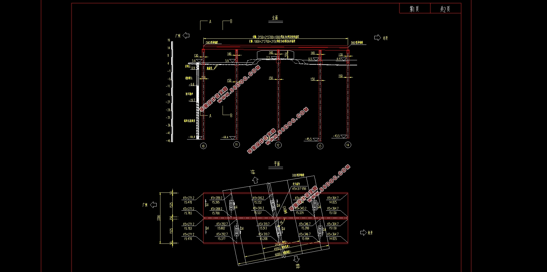
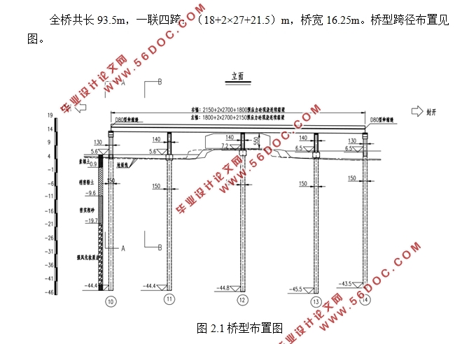
全桥共长93.5m,一联四跨:(18+2×27+21.5)m,桥宽16.25m。桥型跨径布置见图。
2.4技术指标
(1)道路等级:高速公路。
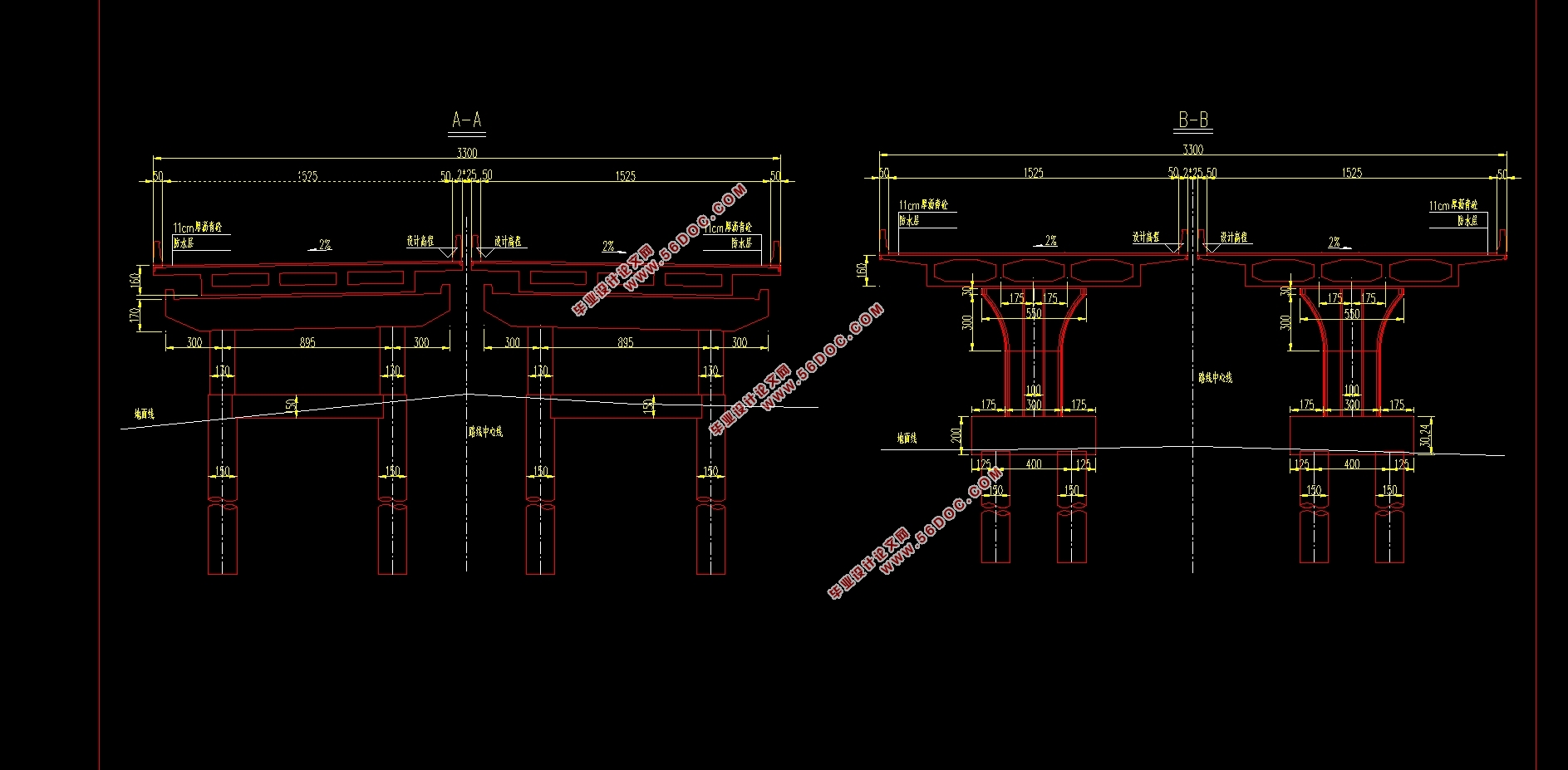
(2)主线桥标准桥宽为33m,0.5m护栏+15.25m行车道+0.5m护栏+2×0.25m分隔带+0.5m护栏+15.25m行车道+0.5m护栏。跨径:(18+2×27+21.5)m。
(3)梁高:梁高1.6m。
(4)桥梁设计基准期:100年。
(5)桥梁设计安全等级:一级。
(6)桥梁设计汽车荷载:公路Ⅰ级。
(7)设计车速:主线桥是100km/h。
2.5主要材料
2.5.1混凝土
(1)沥青混凝土:用于桥面铺装。
(2)C50混凝土:用于预应力混凝土的连续箱梁及下部结构等。
2.5.2钢材
(1)普通钢筋:HRB335钢筋直径均不小于12mm,为热轧的带肋钢筋。
(2)预应力钢绞线:采用高强低松弛钢绞线,公称直径15.2mm,标准抗压强度 ,张拉时锚下控制应力为 。
2.6结构尺寸设计
2.6.1梁高初步确定
本次设计桥梁为一联四跨,全桥桥长为93.5m,梁高取1.6m。


目录
第1章 绪论 1
1.1预应力混凝土连续箱梁桥的发展 1
1.2选题设计思想及意义 1
第2章 桥梁方案设计 3
2.1桥梁方案比选 3
2.2桥梁线性布置 5
2.3技术标准与设计规范 5
2.4技术指标 6
2.5主要材料 6
2.5.1混凝土 6
2.5.2钢材 6
2.6结构尺寸的设计 6
2.6.1梁高的初步确定 6
2.6.2截面类型的确定 7
2.6.3截面细部尺寸的选择 7
第3章 midas/civil建模 9
3.1 midas/civil建模过程 9
3.1.1设定操作环境 9
3.1.2定义材料 10
3.1.3定义截面 10
3.1.4定义变截面/变截面组 11
3.1.5建立节点 13
3.1.6建立单元 13
3.1.7定义时间依存性材料 14
3.1.8定义边界条件及边界组 14
3.1.9定义静力荷载工况 15
3.1.10定义移动荷载工况 15
3.1.11定义结构组 16
3.1.12定义荷载组 17
3.1.13定义施工阶段 17
3.1.14生成荷载组合 18
3.2 Midas/Civil分析过程 19
第4章 主梁内力计算 21
4.1恒载内力计算 21
4.2活载内力计算 22
4.3温度作用下内力计算 24
4.4支座沉降作用下内力计算 30
4.5收缩荷载作用下内力计算 32
4.6徐变荷载作用下内力计算 33
4.7内力组合 35
第5章 预应力钢筋设计 41
5.1.纵向预应力筋估算 41
5.2 预应力筋的布置 46
5.3预应力次内力 49
第6章 预应力损失计算 51
6.1预应力钢筋与管道壁之间的摩擦 51
6.2锚具变形、钢筋回缩和接缝压缩 51
6.3预应力钢筋与台座之间的温差 52
6.4混凝土的弹性压缩 52
6.5预应力钢筋的应力松驰 52
6.6混凝土的收缩徐变 53
6.7预应力损失计算结果 54
第7章 主要截面的验算 62
7.1施工阶段正截面法向应力验算 62
7.2受拉区钢筋的拉应力验算 63
7.3使用阶段正截面抗裂验算 65
7.4使用阶段斜截面抗裂验算 66
7.5使用阶段正截面压应力验算 67
7.6使用阶段斜截面主压应力验算 68
7.7使用阶段正截面抗弯验算 69
7.8使用阶段斜截面抗剪验算 71
第8章 盖梁的设计与验算 73
8.1盖梁内力计算 73
8.2配筋计算 74
8.2.1弯矩作用下正截面配筋计算 74
8.2.2剪力作用时配筋计算 74
8.3抗裂验算 74
第9章 桥墩计算 77
9.1荷载计算 77
9.2截面配筋计算 78
9.3墩柱截面承载力验算 79
第10章 钻孔灌注桩的计算 81
10.1荷载计算 81
10.2桩长计算 81
10.3桩的内力及位移计算 82
10.3.1基本假定 82
10.3.2桩的计算宽度 83
10.3.3桩的变形系数 83
10.3.4计算最大冲刷线处桩身弯矩、水平力及轴向力 83
10.3.5最大冲刷线下深度Z处桩截面上的弯矩及水平压应力 84
10.3.6桩顶纵向水平位移验算 86
10.4桩身截面配筋的计算 87
10.5桩的截面承载力验算 89
参考文献 90
|


