庙台子1号桥(4×40m预应力砼先简支后连续T梁桥)右幅设计(含CAD图)(任务书,开题报告,外文翻译,论文说明书27000字,CAD图纸31张,答辩PPT)
摘要
我国有着悠久的建桥历史,祖先为我国的建桥事业作出了巨大的贡献,留下了许多不朽的篇章,赵州桥,洛阳桥等都闻名于世。我国现在的桥梁建设水平也是处于世界前列的,随着我国经济力量的提高,一大批具有高水平的桥梁陆续出现如苏通大桥,胶州湾跨海大桥。超静定结构的一系列连续梁桥有其特有的优点,结构刚度很大大、桥梁的伸缩缝少而且桥梁的变形小。连续梁桥的快速发展还得益于行车的平稳舒适。预应力结构通过预应力钢绞线对混凝土提前施加压力,不仅充分发挥了混凝土材料的最优特性,而且提高了混凝土构件的抗裂能力,使建筑物,桥梁向轻型化发展,因而预应力混凝上结构现在广泛使用。而且这种结构的跨越能力比钢筋混凝土结构大得多。
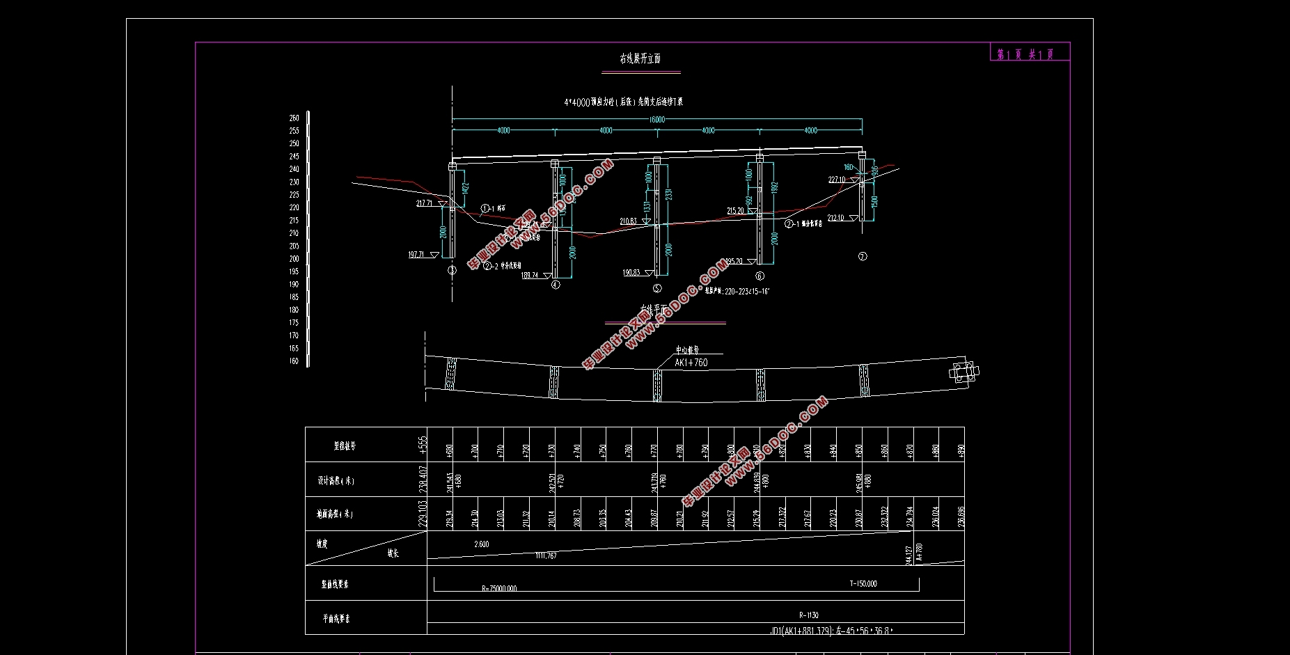
本次设计庙台子1号桥的截面T形,为呼和浩特至北海高速公路上的桥,桥的中心桩号为: K1+760 (A线),公路I级是本桥的设计荷载,上部结构为4×40m的预应力混凝土T形连续桥梁,施工方法为先简支后连续。
本次设计包主要内容为: T梁截面尺寸拟定,主梁内力计算;主梁预应力钢束估算及布置,负弯矩预应力钢筋的估算及布置,主梁截面几何特性计算:钢束预应力损失估算:主梁截面强度与应力验算,主梁端部的局部承压强度验算;主梁变形验算;横隔梁计算,行车道板计算:盖梁计算,墩柱计算,桩基计算等内容。
关键词:连续梁桥预应力砼, T梁,桩柱墩,作用效应都计算,结构验算,有限元分析。
abstract
Our country has a long history of building bridges. Our ancestors have made great contributions to the cause of building bridges in our country, leaving many immortal chapters. Zhaozhou Bridge, Luoyang Bridge and so on are well-known in the world. China's current bridge construction level is also in the forefront of the world. With the improvement of China's economic strength, a large number of high-level bridges have emerged, such as Sutong Bridge, Hangzhou Bay Stone Bridge and so on. Statically indeterminate continuous girder bridges have developed rapidly because of their outstanding features such as large structural stiffness, small deformation, few expansion joints and smooth and comfortable driving. Prestressed structures not only give full play to the characteristics of high-strength materials, but also improve the crack resistance of concrete members and lighten the structure. Therefore, the structure on the pre-stressed concrete has much larger spanning capacity than that on the reinforced concrete structure.
The T-shaped section of Miaotaizi No. 1 Bridge is a bridge on Hohhot-Beihai Expressway. The central pile number of the bridge is K1+760 (Line A). The design load is grade I of the highway. The upper structure is 4*40m prestressed concrete T-shaped continuous beam. The construction method is simple support first and then continuous.
The main contents of this design package are: T-beam section size formulation, main beam internal force calculation; main beam prestressing steel bundle estimation and layout, negative moment prestressing steel bar estimation and layout, main beam section geometric characteristics calculation: steel bundle prestressing loss estimation: main beam section strength and stress calculation, main beam end local compressive strength calculation; main beam deformation calculation; diaphragm beam calculation, Lane slab calculation. Calculations: cover beam calculation, pier column calculation, pile foundation calculation, budget estimates and so on.
Key words: Bridge: Prestressed Concrete Continuous Beam: T Beam, Midas Modeling, Simply Supported and Continuous
1.2.1 设计题目
庙台子1号桥(4*40m预应力砼先简支后连续T梁桥)右幅设计
1.2.2 设计资料
1.桥梁线形布置
平曲线半径: 1130m,由于半径较大, 按直线计算设计。
竖曲线半径:纵断面位于R=75000m的竖曲线上,墩台径向布置。
2.设计标准
荷载标准:公路- I级
桥面净宽:半幅宽11.25m总宽12.5m
结构重要性系数: 1.1


目 录
第1章 绪论 1
1.1 前言 1
1.2 设计内容说明 1
1.2.1 设计题目 2
1.2.2 设计资料 2
1.2.3材料规格 2
1.2.4基本计算数据 2
1.2.5设计依据: 4
第2章桥型方案比选及设计资料 5
2.1 方案比选原则 5
2.1.1 桥梁设计原则 5
2.2方案比选 5
2.2.1方案比选一 6
2.2.2方案比选二 6
2.2.3方案比选三 7
2.3 结构尺寸拟定 8
2.3.1主梁片数与主梁间距 8
2.3.2主梁结构尺寸拟定 8
2.3横截面沿跨长的变化 10
2.4横隔梁的设置 10
2.5毛截面几何特性计算 11
第3章行车道板计算 14
3.1悬臂板荷载效应计算 14
3.1.1永久作用 14
3.1.2可变作用 15
3.1.3承载能力极限状态作用基本组合 15
3.2连续板荷载效应计算 15
3.2.1永久作用 15
3.2.2可变作用 17
3.2.3作用效应组合 18
3.3截面设计、配筋与与承载力验算 19
第4章主梁作用效应计算 21
4.1 结构自重作用效应计算 21
4.2 主梁横向分布系数计算 21
4.3 midas/civil建模过程 23
4.3.1设定操作环境 23
4.3.2定义材料 23
4.3.3定义截面 23
4.3.4定义变截面/变截面组 23
4.3.5建立节点 24
4.3.6建立单元 24
4.3.7定义时间依存性材料 24
4.3.8定义边界条件及边界组 24
4.3.10建立静力荷载工况 25
4.3.11建立移动荷载工况 25
4.3.12施加预应力荷载 25
4.3.13定义荷载组 26
4.3.14划分施工阶段 26
4.4 Midas/Civil分析过程 27
4.4.1生成荷载组合 27
4.4.2模型分析结果 27
4.3.3 PSC设计 30
第5章荷载内力计算 32
5.1恒载内力计算 32
5.2活载内力 33
5.3次内力的计算及内力组合 48
5.3.1温度次内力 48
5.3.2支座沉降次内力 54
5.3.3预应力次内力 56
5.3.4收缩次内力 57
5.3.5徐变次内力 59
5.3.6内力组合 35
6章预应力钢束 41
6.1预应力钢筋设计 41
6.1.1纵向预应力筋估算 41
6.2估算结果 44
6.3 预应力损失 48
6.3.1预应力钢筋与管道壁之间的摩擦σl1 61
6.3.2锚具变形、钢筋回缩和接缝压缩σl2 61
6.3.3预应力钢筋与台座之间的温差σl3 62
6.3.4混凝土的弹性压缩σl4 62
6.3.5预应力钢筋的应力松驰σl5 62
6.3.6混凝土的收缩徐变σl6 62
6.3.7 预应力损失计算结果 63
第7章主梁截面验算 65
7.1承载能力极限状态截面验算 65
7.1.1正截面抗弯验算 65
7.1.2斜截面抗剪验算 66
7.2正常使用极限状态截面验算 68
7.2.1使用阶段正截面抗裂验算 68
7.2.2使用阶段斜截面抗裂验算 68
7.3持久状况和短暂状况构件的应力验算 69
7.3.1使用阶段正截面压应力验算 69
7.3.2使用阶段斜截面主压应力验算 69
7.3.3施工阶段正截面法向应力验算 70
7.3.4受拉区钢筋的拉应力验算 71
7.4 锚下局部承压验算 73
7.4.1局部受压区尺寸要求 73
7.4.2局部抗压承载力计算 74
第8章横隔梁计算 75
8.1确定作用在跨中横隔梁上的可变作用 75
8.2跨中横隔梁的作用效应影响线 76
8.2.1绘制弯矩影响线 76
8.2.2 绘制剪力影响线 78
8.3截面作用效应计算 79
第9章支座计算 80
9.2确定支座平面尺寸 80
9.2确定支座的厚度 82
9.3验算支座偏转情况 82
9.4验算支座的抗滑稳定性 83
第10章.下部结构 84
10.1盖梁计算 84
10.1.1荷载计算 85
10.1.2内力计算 91
10.2.3截面配筋设计及承载力校核 93
10.3,桥墩墩柱设计 95
10.3.1荷载计算 95
10.3.2截面配筋及最大应力计算 98
10.4钻孔桩计算 100
10.4.1荷载计算 100
10.4.2桩长计算 102
10.4.3桩的内力计算(m法) 103
10.4.4桩身截面配筋与承载力验算 105
附录: 108
附录A 108
参考文献 116
|


