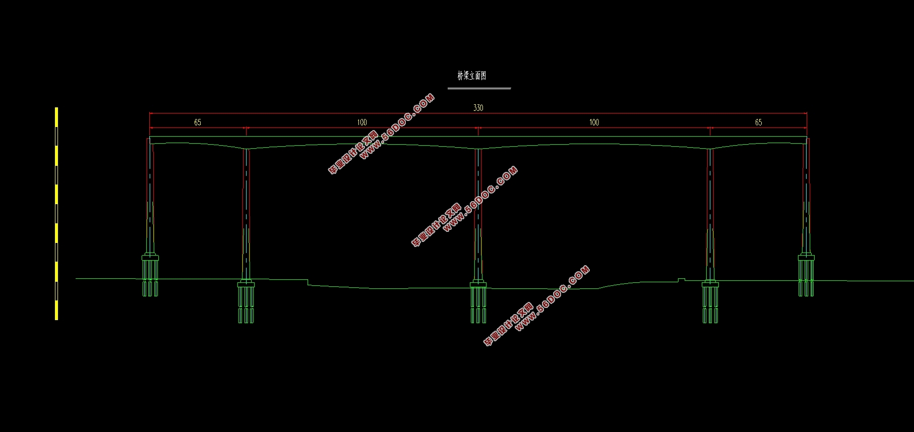
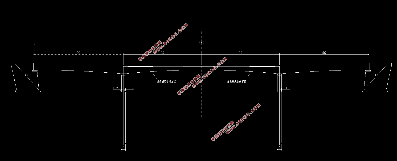
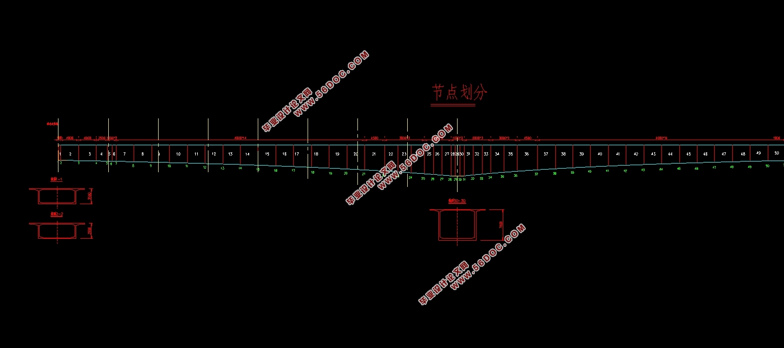
基于UHPC的150m跨度连续梁桥结构设计(90m+150m+90m)(含CAD图)(任务书,开题报告,外文翻译,论文说明书17000字,CAD图纸6张)
摘 要
进入21世纪后,我国桥梁的技术水平不断地提高,混凝土的性能越来高,桥梁结构类型也越来越新颖,连续梁桥的跨径可以越做越大。超高性能混凝土UHPC拥有着普通混凝土无法比拟的抗压、抗拉和耐久性能,引得越来越多人的研究和关注,并广泛的被应用于实际的工程中。
本设计在根据毕业设计的要求下,设计完成了一座主梁是应用UHPC材料的三跨连续梁桥。设计开始先做方案的比选,在合理的范围内选出一座安全可靠、经济合理、美观环保的桥梁。方案比选完成后,确定桥梁上部结构的具体尺寸,划分施工阶段,确定桥面铺装,绘制相应CAD图形,最后通过Midas Civil有限元分析软件进行模拟分析。建模过程中根据桥梁的截面特点划分节点单元,施加各类荷载,得出内力包络图,根据抗裂性要求,布置纵向的预应力筋。按规范要求组合内力,验算施工阶段和使用阶段的抗弯、抗扭能力。
最后得到以下结论:推荐设计方案为跨径组合(90m+150m+90m)的新型UHPC三跨连续梁桥。本设计的特点是由于布置了密集的横隔板具有更好的横向抗弯内力,梁壁的厚度更小,刚度更大,抗裂内力更强等。
关键词:超高性能混凝土(UHPC);连续梁桥;预应力混凝土;结构设计
Abstract
After entering the 21st century, the technical level of bridges in China has been continuously improved, the performance of concrete has become higher and higher, and the types of bridge structures have become more and more novel. The span of continuous beam bridges can be made larger and larger. Ultra-high performance concrete UHPC possesses the compressive, tensile and durability properties unmatched by ordinary concrete, attracting more and more people's research and attention, and is widely used in practical engineering.
This design is designed according to the requirements of graduation design. A main beam is a three-span continuous beam bridge using UHPC material. The design begins with the comparison of the first plan, and selects a safe, reliable, economical, beautiful and environmentally friendly bridge within a reasonable range. After the comparison of the schemes is completed, the specific dimensions of the superstructure of the bridge are determined, the construction phase is divided, the deck pavement is determined, the corresponding CAD drawings are drawn, and the simulation analysis is performed by Midas Civil finite element analysis software. During the modeling process, the node elements are divided according to the cross-section characteristics of the bridge, various types of loads are applied, and the internal force envelope diagram is obtained. According to the crack resistance requirements, the longitudinal prestressing tendons are arranged. The internal force is combined according to the requirements of the specification to check the bending and torsion resistance of the construction phase and the use phase.
Finally, the following conclusions are drawn: The recommended design is a new UHPC three-span continuous beam bridge with a span combination (90m+150m+90m). The feature of this design is that due to the arrangement of dense transverse partitions, it has better lateral bending internal force, the thickness of the beam wall is smaller, the rigidity is larger, and the internal force against cracking is stronger.
Key Words: Ultra-High Performance Concrete(UHPC); continuous beam bridge; prestressed concrete;structural design
1.3 本文主要设计内容
本文将设计出一座三跨UHPC连续梁桥,拟采用单向预应力UHPC薄壁箱梁结构。在方案比选后,对全桥进行施工阶段模拟分析和成桥阶段模拟分析,对桥梁在恒载和活载作用下的应力以及承载能力进行验算,最终得出结果。
第2章 桥跨总体布置及结构尺寸拟定
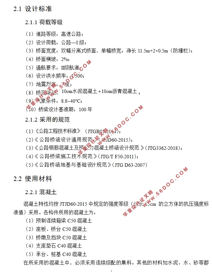
2.1 设计标准
2.1.1荷载等级
(1)道路等级:高速公路;
(2)设计荷载:公路—I级;
(3)桥面宽度:双幅分离式桥面,单幅桥宽:净长11.5m+2×0.5m(防撞栏);
(4)桥面横坡:2%;
(5)通航要求:Ⅱ级航道;
(6)设计洪水频率:1/300;
(7)地震烈度:7度;
(8)桥面铺装: ;
(9)气象条件:8.8~40℃;
(10)桥梁设计基准期:100年
2.1.2 采用的规范
(1) (JTGB01-2014);
(2)《 》(JTJD60-2015);
(3)《 》(JTG3362-2018);
(4)《 》(JTG/T F50-2011);
(5)《 》(JTG D63-2007)
2.2 使用材料
2.2.1混凝土
混凝土特性均按JTJD60-2015中规定的强度等级(边长15cm 的立方体的抗压强度标准值)采用。各构件所用的混凝土为:
(1)预制连续箱梁C50混凝土
(2)座板、桥台C50混凝土
(3)桥墩及挡块C50混凝土
(4)支座垫石C40混凝土
(5)承台、桩基C40混凝土
在所采用的混凝土中,必须采用连续级配的集料。


目 录
第1章 绪论 1
1.1 概述 1
1.2 UHPC新型梁桥结构 1
1.3 本文主要设计内容 2
第2章 桥跨总体布置及结构尺寸拟定 3
2.1 设计标准 3
2.1.1荷载等级 3
2.1.2 采用的规范 3
2.2 使用材料 3
2.2.1混凝土 3
2.2.2预应力钢材 4
2.2.3普通钢筋与箍筋 4
2.2.4锚具 4
2.2.5其他材料 4
第3章 桥型方案比选 5
3.1 方案比选的意义及原则 5
3.2 初选方案 5
3.3 方案一:UHPC新型预应力混凝土连续梁桥 6
3.3.1 桥跨设计 6
3.3.2 上部结构 6
3.3.3 主要工程数量 8
3.4 方案二:普通预应力混凝土连续梁桥 8
3.4.1 桥跨设计 8
3.4.2 主梁上部结构 8
3.4.3 主要工程数量 10
3.5 方案三:混凝土斜拉桥 10
3.5.1 主要材料 10
3.5.2 桥跨布置 10
3.5.3 主要工程数量 10
3.6 方案比选 13
第4章 UHPC连续梁桥总体布置 14
4.1 桥型布置 14
4.1.1 孔径布置 14
4.1.2 桥梁截面特性 14
4.1.3 桥面铺装 15
4.1.4 桥梁下部结构 15
4.1.5 使用材料 16
第5章 Midas计算模型的建立 18
5.1 选用材料 18
5.2 全桥节点、单元的划分 18
5.2.1 划分单元原则 18
5.2.2 桥梁具体单元划分 18
5.3 荷载的定义 19
5.4 全桥施工节段的划分 19
5.4.1 桥梁施工阶段划分原则 19
5.4.2 施工阶段划分 19
第6章 主梁内力计算 23
6.1 恒载内力计算 23
6.1.1自重及二期恒载 23
6.1.2 悬臂拼装阶段内力 23
6.1.3 边跨合龙阶段内力 24
6.1.4 中跨合龙阶段内力 24
6.1.5 桥面铺装时的内力 25
6.2 活载内力计算 25
6.2.1 自振频率 26
6.2.2 移动荷载引起的内力 26
第7章 预应力钢束的估算与布置 28
7.1 钢束估算 28
7.1.1 按承载能力极限计算时满足正截面强度要求估算 28
7.1.2 按正常使用极限状态的应力要求估算 29
7.1.3 按正截面抗裂性要求估算 30
7.2 预应力钢束布置 38
7.3 预应力损失 40
7.3.1 摩阻损失 40
7.3.2 锚具变形损失 40
7.3.3 混凝土的弹性压缩损失 41
7.3.4 预应力的应力松弛损失 41
7.3.5 收缩徐变损失 41
7.4 预应力计算 42
第8章 桥梁内力组合 44
8.1 承载能力极限状态下的作用效应组合 44
8.2 正常使用极限状态下的作用效应组合 44
8.3 Midas Civil内力组合 46
第9章 主梁截面验算 48
9.1 正截面抗弯承载力验算 48
9.2 斜截面抗剪承载力验算 51
9.3 持久状况构件应力验算 54
9.3.1 使用阶段正截面受压区混凝土的压应力验算 54
9.3.2 使用阶段正截面受拉区预应力筋的拉应力验算 61
第10章 行车道板验算 62
第11章 结论 64
参考文献 65
致 谢 67
|


