G15高速公路小箱梁桥结构设计(跨径为30m)(含CAD图)(任务书,开题报告,论文说明书20000字,CAD图纸21张)
摘要
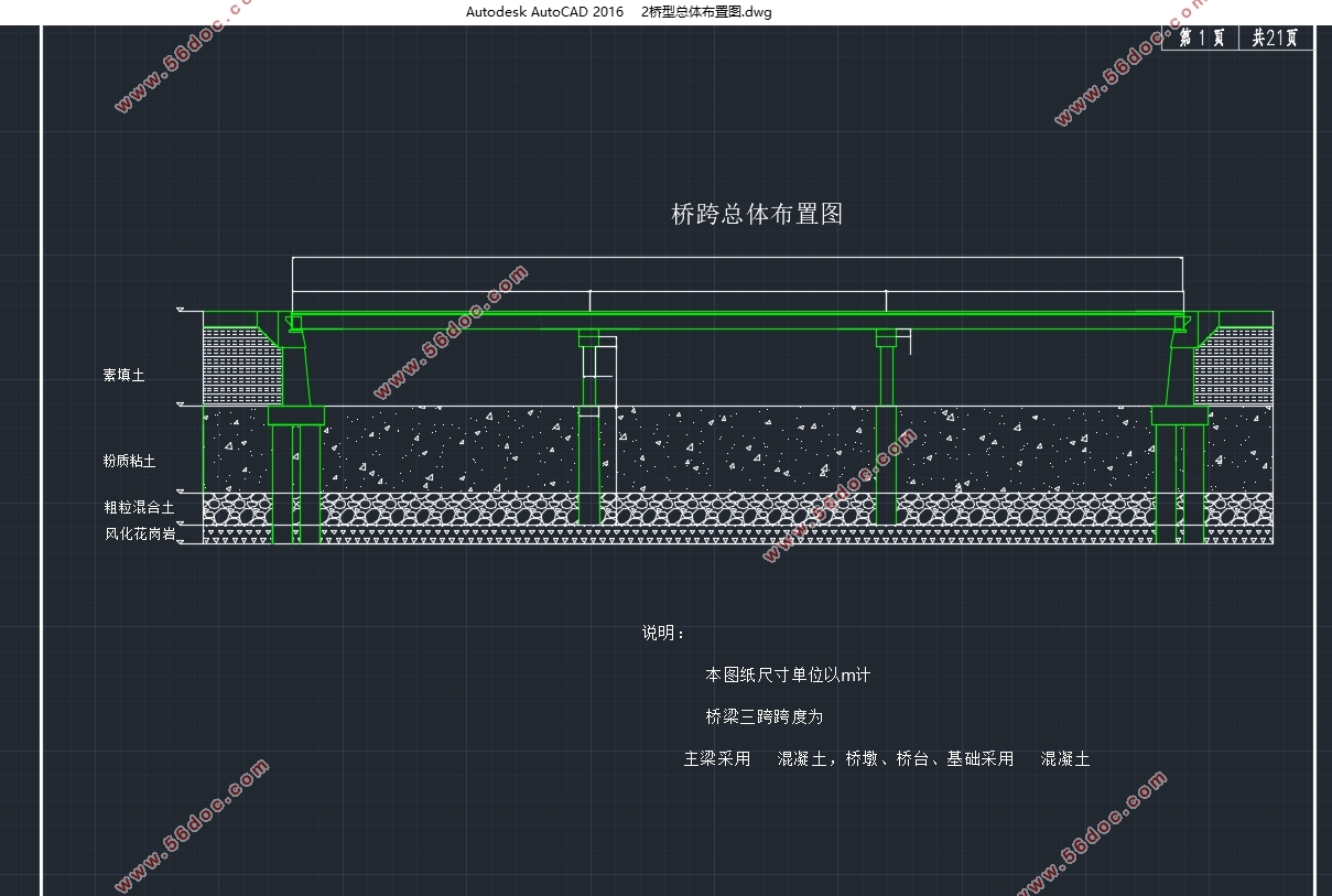
G15高速公路小箱梁桥设计为跨径为30m的 ,该桥采用4车道。上部为装配式部分 。后张法 在设计荷载下按 ,主梁配筋要采用预应力筋和非预应力筋的混合配筋。下部结构乃钢筋混凝土圆形的墩。桥墩基础乃钻孔灌注桩基础。盖梁可按简支梁来计算盖梁内力和 。
本文的思路是分为上部结构和下部结构,上部结构有以下几部分:结构 拟定,主梁 计算,主梁 估算及布置,主梁 性计算,钢束 算,主梁 应力验算,主梁端部 强度验算,主 验算,横隔梁计算,行 计算。下部结构有:盖梁计算,墩柱计算,桩基计算。
关键词: ,箱梁,桩基础
Abstract
The G15 highway girder bridge is designed for 30m prestressed concrete beam bridge with 4 lanes.Upper for assembling part prestressed concrete simply supported beam bridge. Post tensioned prestressed concrete box girder under the design load according to the partially prestressed concrete class a component design, beam main reinforcement by prestressed tendons and non prestressed reinforcement with mixed reinforcement. Substructure for reinforced concrete circular piers. Pier foundation for bored pile foundation. Pier beam can according to the simple beam calculation of capping beam internal force and pillar vertical reaction force.
In this paper, the idea for the upper structure and the lower structure, the upper structure has the following parts: structure size sketch, girder internal force calculation, girder prestressed steel beam estimates and arrangement, girder section geometric properties calculation, steel beam prestress loss estimates, beam intensity and strength checking, on the end part of the main beam of local bearing strength calculation, beam deformation checking, diaphragm beam calculation, calculate carriageway plate. The lower structure: Calculation of capping beam, pier column calculation and calculation of pile foundation.
Keywords: prestressed concrete simply supported beam, box girder, pile foundation
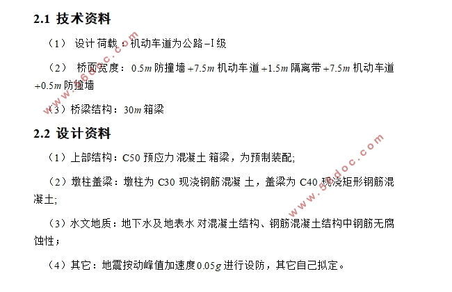
2.1 技术资料
(1) 设计 :机动车道为公路 级
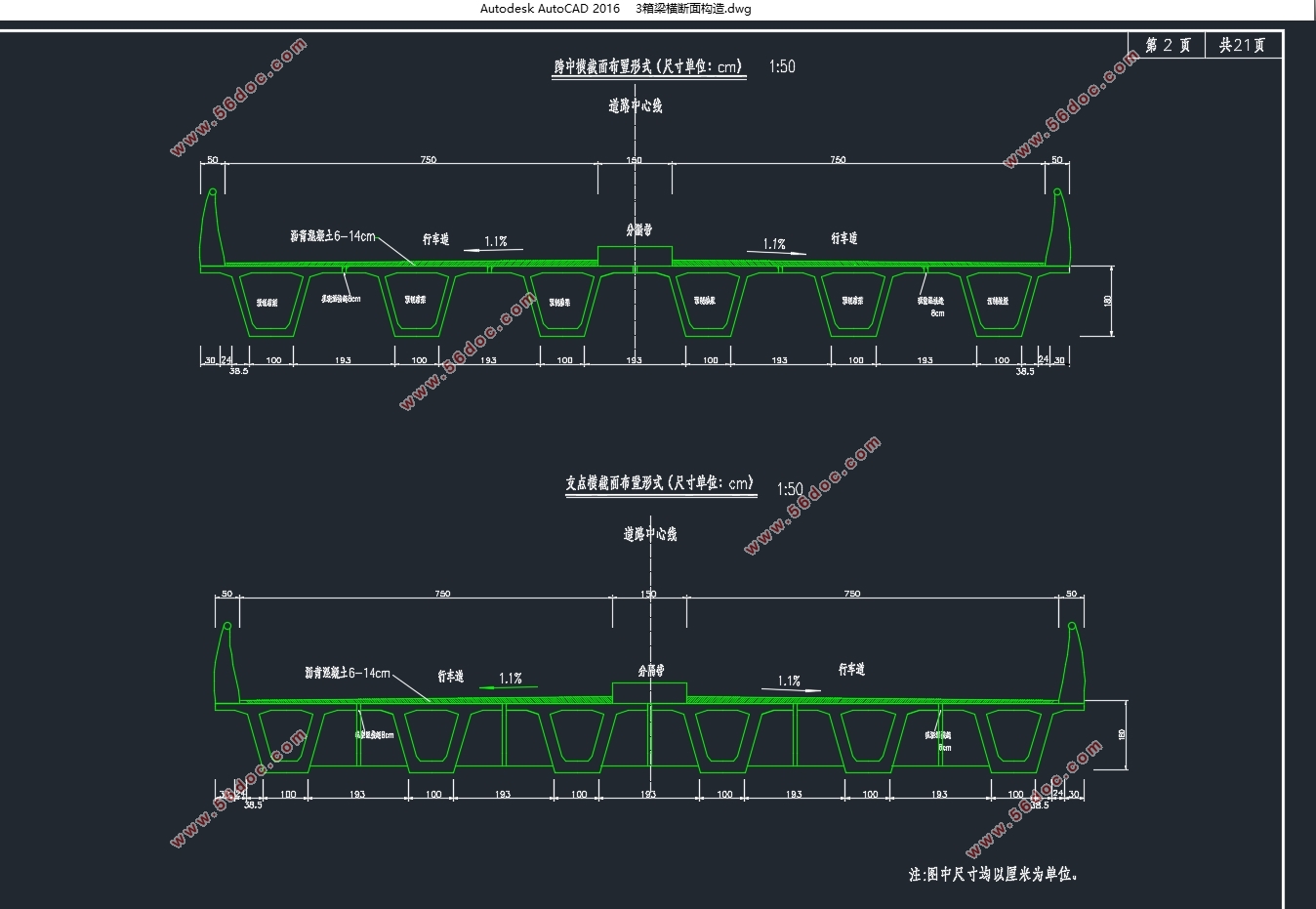
(2) 桥面宽度: 防撞墙 机动车道 隔离带 机动车道 防撞墙
(3)桥梁结构: 箱梁
2.2 设计资料
(1)上部结构:C50预应力 箱梁,为预制装配;
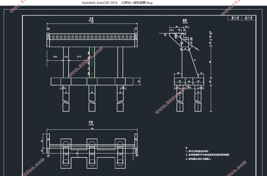
(2)墩柱盖梁:墩柱为C30现浇钢筋 土,盖梁为C40现浇矩形钢筋混凝土;
(3)水文地质:地下水及 对混凝土结构、钢筋混凝土结构中钢筋无腐蚀性;
(4)其它:地震按动峰值加速度 进行设防,其它自己拟定。
3.1 主梁间距与主梁片数
主梁间距采用的是2.85m,一共6片( ),现浇湿接缝长8cm
目 录
第1章 绪论 1
第2章 设计资料 3
2.1 技术资料 3
2.2 设计资料 3
第3章 结构尺寸 4
3.1 主梁间距与主梁片数 4
3.2 主梁尺寸拟定 4
3.2.1 箱梁高度 4
3.2.2 箱梁顶,底,腹板的厚度 4
3.2.3 横截面沿跨长变化 5
3.2.4 横隔梁设置 5
3.2.5 截面效率指标 5
第4章 主梁内力计算 8
4.1 恒载内力计算 8
4.1.1一期恒载(主梁自重) 8
4.1.2 二期恒载 8
4.1.3 恒载内力 9
4.2 活载内力计算 9
4.2.1冲击系数和车道折减系数 9
4.2.2 主梁的荷载横向分布计算 10
4.2.3 计算活载内力 19
4.3 内力组合 27
第5章 预应力钢筋面积估算及钢束布置 30
5.1 预应力钢筋面积估算 30
5.2 预应力钢束布置 31
5.2.1 确定跨中及锚固端截面的钢束位置 32
5.2.2 钢束起弯角和线型的确定 32
5.2.3 钢束几控制要素计算 33
5.2.4 各截面钢束位置及倾角计算 34
5.2.5 钢束的长度计算 36
5.3 非预应力钢筋截面积估算及布置 36
第6章 截面面积及惯矩计算 38
6.1施工到运营三个阶段 38
6.2计算数据 38
第7章 主梁截面强度验算 41
7.1 截面强度验算 41
7.1.1 正截面强度验算 41
第8章 钢束预应力损失 45
8.1 预应力钢束与管道壁的摩擦损失 45
8.2 由锚具变形,钢束回缩引起的预应力损失 45
8.3 预应力钢筋分批张拉时混凝土弹性压缩引起的应力损失 48
8.4 钢筋松弛引起的预应力损失 49
8.5 混凝土收缩徐变引起的预应力损失 49
第9章 截面应力验算 53
9.1 短暂状态的正应力验算 53
9.2 持久状态的正应力验算 53
9.2.1 截面混凝土的正应力验算 53
9.2.2 持久状态下的预应力钢筋的应力验算 55
9.2.3 持久状态下的混凝土主应力验算 55
9.3 抗裂性能验算 58
9.3.1 作用短期效应组合作用下的正截面抗裂验算 58
9.3.2 作用短期效应组合作用下的斜截面抗裂验算 59
9.4 主梁变形(挠度)计算 61
9.4.1 荷载短期效应组合下主梁挠度验算 61
9.4.2 预加力引起的上拱度计算 62
9.4.3 预拱度的设置 62
第10章 梁端锚固区的局部承压验算 63
10.1 局部承压尺寸要求 63
10.2 局部抗压承载力计算 64
第11章 横隔梁内力计算 66
11.1确定作用在横隔梁的计算荷载 66
11.2.1绘制弯矩影响线 67
11.2.2绘制剪力影响线 68
11.3截面内力计算 68
11.4截面配筋计算 69
第12章 行车道板计算 71
12.1 翼缘板内力计算及配筋 71
12.1.1 每延米板上的恒载g 71
12.1.2 每米宽板条的内力 71
12.1.3 内力组合 72
12.1.4 截面设计,配筋与强度验算 72
12.2 腹板间连续单向板的内力计算及配筋 74
12.2.1 弯矩计算 74
12.2.2 支点剪力计算 74
12.2.3 内力组合 75
12.2.4 截面设计,配筋与强度验算 75
第13章 盖梁、柱式桥墩和钻孔灌注桩计算 78
13.1桥墩尺寸 78
13.2 盖梁计算 78
13.2.1 荷载计算 78
13.2.2 内力计算 84
13.2.3 盖梁配筋计算 88
13.3 桥墩墩柱计算 90
13.3.1 荷载计算 90
13.3.2 截面配筋计算 91
13.4 钻孔灌注桩计算 95
13.4.1 荷载计算 95
13.4.2 桩长计算 95
13.4.3 桩的内力计算 96
13.4.4 墩顶纵向水平位移验算与桩身材料截面强度验算 99
13.4.5 桩身材料强度验算 100
参考文献 104
致谢词 105
|
