高墩大跨(66+120+66)m预应力混凝土连续刚构桥设计(含CAD图)
来源:56doc.com 资料编号:5D25204 资料等级:★★★★★ %E8%B5%84%E6%96%99%E7%BC%96%E5%8F%B7%EF%BC%9A5D25204
资料以网页介绍的为准,下载后不会有水印.资料仅供学习参考之用. 密 保 惠 帮助
资料介绍
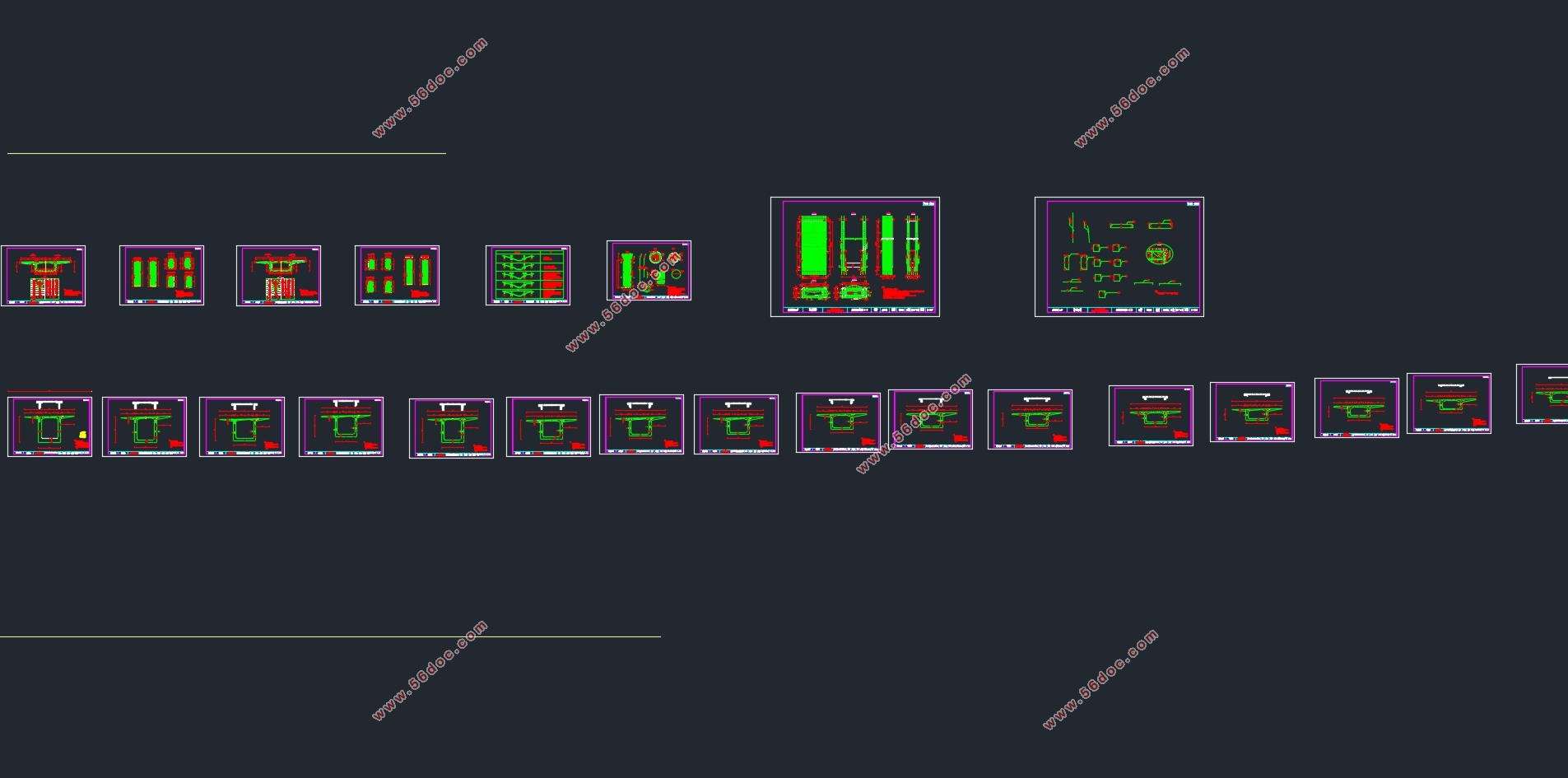
高墩大跨(66+120+66)m预应力混凝土连续刚构桥设计(含CAD图)(任务书,开题报告,论文计算书21000字,CAD图33张)
摘 要
本毕业设计题目为连续刚构桥,它的跨径为 。这种桥型构造刚度好、行车平稳舒适、便于养护、抗震性能好、且墩梁固结利于悬臂施工。因此,在最近的一些年里,连续刚构桥的应用更加普遍。
在进行桥梁的设计工作之前,需要对桥梁工程、基础工程以及结构力学原理等科目进行一个综合的回顾。做到能对所需设计的桥型的各个方面比如受力等的一个充分的了解。这样在进行桥梁设计时能更加的轻松方便。并且还需要熟悉MIDAS/CIVIL的应用,这有利的模型结构的正确建立。
进行设计的第一步便是熟悉桥址的地形地貌以及地质情况。然后开始进行桥型的比选。本设计从受力及优缺点上对几个桥梁结构进行了比较,最终选定连续刚构桥为本设计的桥型。然后便是初步拟定桥梁的几何尺寸,这里需要多参考有关资料作出合适的选择。
然后,本设计通过MIDAS/CIVIL软件,利用所拟定的尺寸,便可以建立出一次成桥的模型。施加恒载经过计算得到内力结果,对预应力束进行了估计。接着便可导入钢束及移动荷载和施工阶段等,进行各阶段的应力验算如正截面主压应力验算等。
除此之外,本设计还考虑了预应力损失及次内力可能会对结构所产生的影响并对结果进行分析,并添加车辆荷载及收缩徐变等确保桥梁设计的安全。最后,本设计对桥梁结构的行车道板、下部结构的设计进行了手算。
参考Midas的计算结果,并通过人工辅助验算,经过分析表明,本次毕业设计方法正确,施工阶段与使用阶段截面内力与应力均符合要求,完成了设计任务。
关键词:Midas;连续刚构桥;内力验算;桥梁结构
Abstract
The graduation design is about the design of continuous rigid frame bridge. its span is 66+120+66m. This bridge structure is good at its rigidity, and it is comfortable to drive on it and the pile beam consolidation makes it easier to construct. Therefore, in recent years, the application of continuous rigid frame bridge is more common.
Before the bridge design work, the need for bridge engineering, basic engineering and structural mechanics and other subjects to conduct a comprehensive review. So as to be able to design the bridge of the various aspects of the force. So when we design the bridge that can be more relaxed and convenient. And we also need to be familiar with the Midas software application, which is conducive to the correct establishment of the model structure.
The first step in the design is familiar with the topography of the bridge site and geological conditions. And then we can start to choose the bridge type of comparison. The design of the bridge from the force and the advantages and disadvantages of several bridge structures were compared. The continuous rigid bridge is the final selection of for the design of the bridge. And then we should decide the initial development of the bridge geometry, where need for more reference to the information to make the appropriate choice.
Then, we can start Midas software by using the proposed size.We can build a bridge model. The results from the model is estimated to calculate the number of the prestressed beam. And then the steel beam and mobile load construction stage can be imported in the model.Now we can start the various stages of the internal force calculation, such as the main section of the main compressive stress calculation.
In addition, the design also takes the impact of prestress loss and secondary forces on the structure into account and get the results of the analysis. The design add vehicle load and shrinkage into the model and so on to ensure the safety of bridge design. Finally, the design of the bridge deck and the lower structure is done by hand.
According tothe Midas calculation results and through manual checking.The results of the analysis shows that the graduation design method is correct.The construction phase and the use of section of the internal force and stress are in line with the requirements and the design taskis completed.
Key words:Midas; continuous rigid frame bridge; internal force checking; bridge structure
目录
摘要 I
Abstract II
第1章桥型方案的比选 1
1.1 设计初始资料 1
1.1.1 桥位以及水文情况 1
1.1.2 工程地质概况 2
1.1.3 设计标准及规范 5
1.2 方案比选 5
1.2.1 方案一:三跨预应力混凝土连续刚构桥 5
1.2.2 方案二:三跨连续梁桥 6
1.2.3 方案比较 8
1.3 连续刚构桥简介 9
第2章桥梁总体布置及结构主要尺寸 11
2.1 桥跨布置 11
2.2 上部结构尺寸拟定 11
2.2.1 跨度 11
2.2.2 主梁高度 11
2.2.3 箱梁腹板厚度 12
2.2.4 箱梁底板厚度 12
2.2.5 箱梁顶板厚度 12
2.3 下部结构尺寸拟定 14
2.3.1 墩身尺寸的拟定 14
2.3.2 桩基础尺寸的拟定 14
2.4 主梁分段与施工阶段的划分 15
2.4.1 分段原则 15
2.4.2 具体分段 15
2.4.3 施工方案及注意事项 15
第3章建模 17
3.1 概述 17
3.2 模型的建立 17
3.2.1 节段的划分 17
3.2.2 材料参数 17
3.2.3 荷载参数 18
3.2.4 截面的定义以及边界条件的添加 19
3.2.5 施工阶段的定义 19
3.2.6最终模型 20
第4章桥梁结构内力计算 21
4.1 桥梁恒载内力计算 21
4.1.1 计算阶段划分 21
4.1.2 施工阶段内力计算 21
4.2 桥梁活载内力计算 26
4.2.1 横向分布系数 26
4.2.2 冲击系数 26
4.2.3 人群荷载 26
4.2.4 基础变位 26
第5章预应力钢筋设计 28
5.1 纵向预应力筋估算 28
5.1.1 手算原理及方法 28
5.1.2 手算电算结果及对比 31
5.2 预应力损失及有效预应力计算 32
5.2.1 预应力筋与管道之间的摩擦引起的预应力损失 32
5.2.2锚具变形、钢筋回缩和接缝压缩引起的应力损失 33
5.2.3 预应力钢筋与台座之间的温差引起的损失 33
5.2.4弹性压缩损失 34
5.2.5 钢筋松驰引起的应力损失 34
5.2.6 混凝土收缩和徐变引起的预应力损失 35
5.2.7 预应力损失计算结果 35
第6章次内力计算及内力组合 38
6.1 预应力次内力 38
6.1.1 预应力次内力计算方法 38
6.1.2 预应力次内力计算结果 38
6.2 收缩次内力 39
6.3 徐变次内力 41
6.3.1 徐变变形对结构内力的影响 41
6.3.2 徐变次内力计算方法 41
6.3.3 徐变次内力计算结果 42
6.4 温度次内力 43
6.4.1 温度变化对结构的影响 43
6.4.2 温度变化次内力计算方法 44
6.4.3 温度次内力计算结果 44
6.5 荷载组合 46
6.5.1 作用分类和作用效应 46
6.5.2 按承载能力极限状态组合 46
6.5.3 按正常使用极限状态组合 48
第7章主要截面验算 52
7.1承载能力极限状态截面验算 52
7.1.1 计算依据 52
7.1.1计算结果 52
7.2 正常使用极限状态截面验算 54
7.2.1 施工阶段正截面法向应力验算 54
7.2.2 正截面抗裂验算 56
7.3 扰度验算 59
第8章行车道板计算 60
8.1中间单向板计算 60
8.1.1 恒载内力 60
8.1.2 活载内力 60
8.1.3 荷载组合 61
8.2外边梁悬臂板内力计算 61
8.2.1 恒载内力 61
8.2.2 活载内力 62
8.2.3 荷载组合 62
8.3配筋设计 63
8.3.1 支点处配筋 63
8.3.2 跨中配筋 63
第9章下部结构计算 65
9.1桥墩计算 65
9.1.1 内力计算 65
9.1.2 截面设计 65
9.1.3 截面复核 66
9.2钻孔灌注桩计算 66
9.2.1 基本假定 66
9.2.2 桩径桩长拟定 67
9.2.3 桩基础内力计算 67
9.2.4 桩基础内力验算 72
9.2.5 桩身配筋计算 73
参考文献 75
|
