跨径99m下承式钢管混凝土系杆拱桥设计(含CAD图)(任务书,开题报告,设计说明书20000字,CAD图纸26张)
摘要
钢管混凝土是一种受压能力很强的材料,所以在以承压为主的拱桥中得到广泛的应用。钢管混凝土拱桥较之传统的圬工拱桥与钢筋混凝土拱桥,因其材料强度的提高与施工的方便,使其具有很强的表现力。
本次毕业设计题目为下承式钢管哑铃型混凝土系杆拱桥,它的跨径是99m。首先根据设计经验及构造要求拟定了主梁的主要构造和相关细部尺寸;考虑到桥梁所处的地形地貌,墩身采用了4.316m高的柱式墩;根据地质情况选用摩擦桩作为基础。其次确定施工方法,采用少支架现浇施工。
之后,利用MIDAS/CIVIL软件进行结构有限元分析。根据拟定桥梁尺寸建立桥梁基本模型,进行内力分析、预应力筋的估算与布置以及截面验算。建模时考虑了混凝土收缩徐变、温度、等因素的影响,然后进行荷载组合,并根据荷载组合结果.进行了相关次内力的分析。同时,进行了行车道板、锚下局部承压、桥墩及基础的相关手算。并对钢筋混凝土结构部分进行配筋计算和强度验算。最后对桥面板、吊杆等构件进行验算,满足应力及强度要求。
分析结果表明,本次设计计算方法正确,内力分布合理,完成设计任务的要求。
关键词:下承式钢管混凝土系杆拱桥;结构分析;MIDAS/CIVIL
Abstract
Concrete-filled steel tube is a kind of material with strong compression ability.Compared with traditional masonry arch bridge and reinforced concrete arch bridge, concrete-filled steel tubular arch bridge has a strong expressive force due to the improvement of material strength and the convenience of construction.
This graduation design topic is the steel pipe dumbbell type concrete arch bridge, its span is 99m. Based on the design experience and construction requirements, the main structure and the relevant details of the main girder are proposed. In consideration of the topography of the bridge, the pier adopts a column pier with a height of 4.316m. The friction pile is selected as the foundation according to geological conditions. Secondly, the construction method is determined, and the construction of less stents is adopted.
After that, the MIDAS/CIVIL software was used for finite element analysis. According to the proposed bridge size, the basic model of the bridge is established, and the calculation and layout of the internal force analysis and the prestressing tendon are carried out. The influence of concrete shrinkage and creep, temperature and other factors was considered in modeling, then the load combination was carried out, and the analysis of relevant secondary forces was carried out according to the result of load combination. At the same time, the related hand calculation is carried out on the road plate, the local pressure under the anchor, the bridge pier and the foundation. In addition, the reinforcement calculation and strength checking of reinforced concrete structure are carried out. Finally, the bridge panel, hanger rod and other components are checked to meet the requirements of stress and strength.
The analysis results show that the design calculation method is correct, the internal force distribution is reasonable, and the design task is completed.
1.3 设计基本资料
1.3.1 总体设计
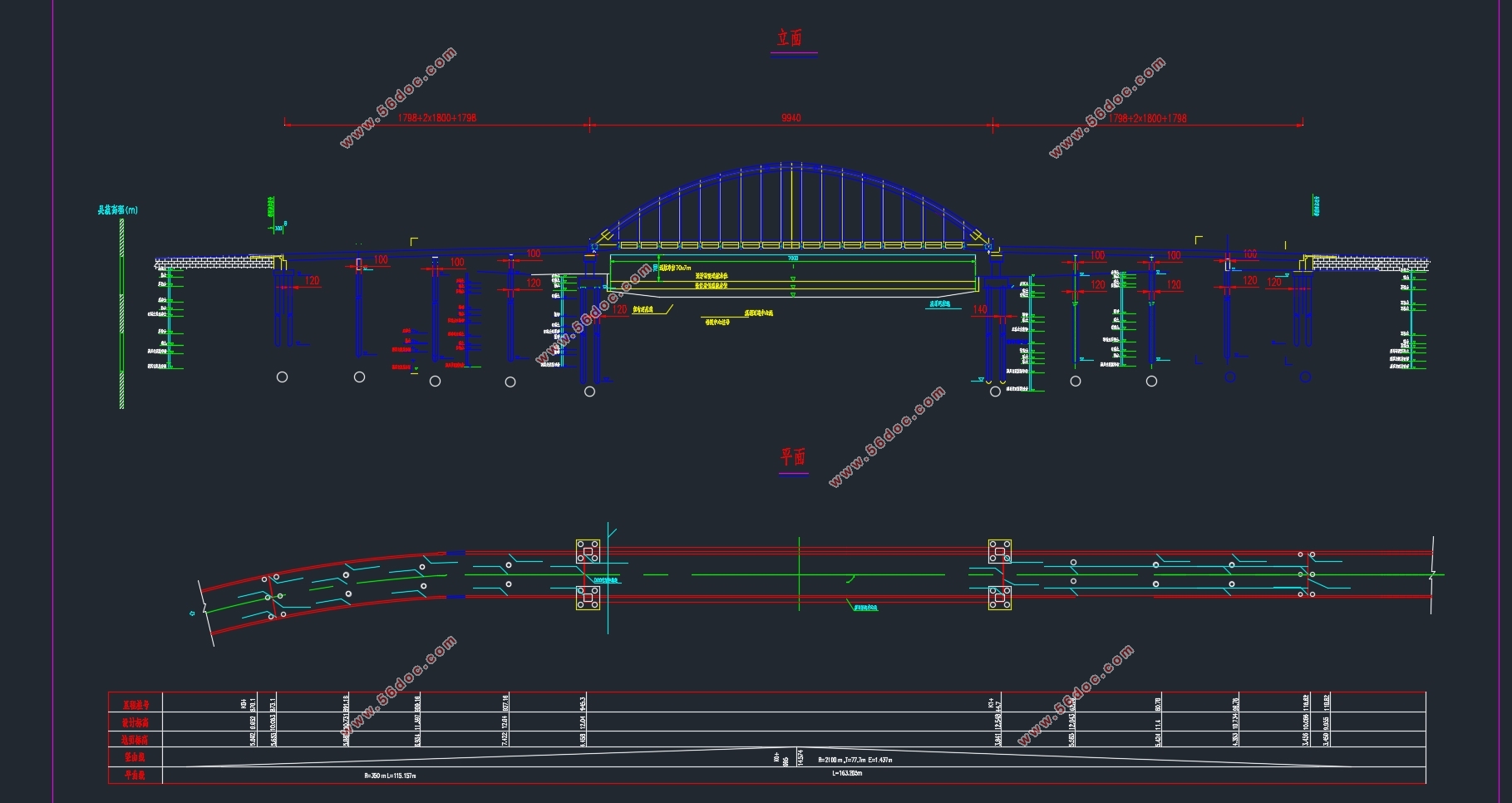
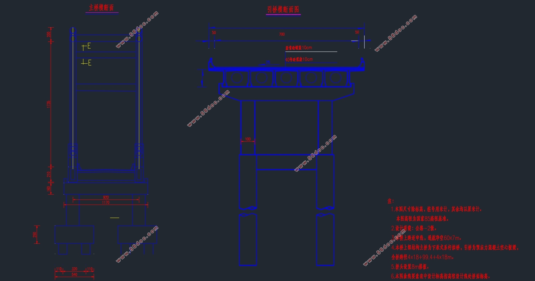
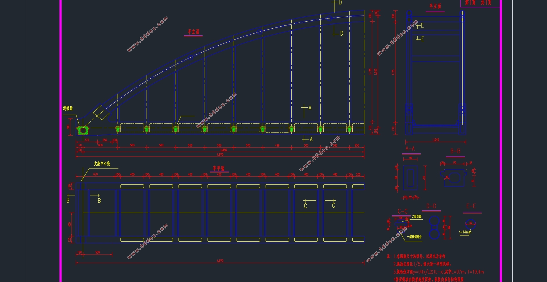
拱桥主跨99m,系梁为少支架现浇施工,主拱分段采用吊装拼装焊接。设计荷载为公路2级:车道荷载q =7.8kN,P =270kN。设计车速为30km/h,桥梁环境类别为Ⅰ类,桥涵结构设计基准期为100年。
主桥为99m下承式钢管混凝土系杆拱桥,引桥是两侧各(4*18)的装配式预应力混凝土组合箱梁。全桥总长244m,共布置了四道伸缩缝,其余的部分为桥面连续。
下部则选用肋板台、柱式墩和钻孔灌注桩基础。本设计中主要运用的软件为midas软件来对上部结构进行设计,通过在MADAS软件中建立有限元模型,从而利用软件对桥梁进行分析计算。在使用Madis/civil分析之前,必须对全桥结构进行离散化,划分单元节点,有限元是表示实际连续域离散单元的集合,结构通过不同的节点连接成不同的单元建立,从而产生荷载并进行设计,单元设置的数量也是一个很重要的过程,如果单元设置过多,将会增加很多工程量,如果单元设置过少,模型设计的精度也会随之降低。因此,我们要在一定准度和精度的基础上,对MADAS单元进行合理的数量选择,并且也要和施工情况结合起来。
1.3.2 主要技术指标
在本设计中采用的主要技术标准如下:
设计荷载:公路2级;
竖曲线最小半径:桥梁凸曲线为5000m
标准冻深:1.0m
最大正温差:30゜C;最大负温差:30゜C


目 录
Abstract III
第1章 桥梁设计资料概况 1
1.1 设计初始资料 1
1.2 桥梁设计方案比较 1
1.2.1主桥桥型方案比选 1
1.3 设计基本资料 4
1.3.1 总体设计 4
1.3.2 主要技术指标 5
1.3.4主要材料 5
1.4 桥梁结构尺寸拟定与设计 6
1.4.1 主桥上部结构拟定 6
1.4.2 拱肋钢管混凝土结构拟定 6
1.4.3 预应力加劲梁结构拟定 7
1.5 主桥施工流程 7
1.6 MIDAS/CIVIL建立模型详细部分 10
第2章 拱肋内力计算 14
2.1 恒载内力计算 14
2.1.1 基本概况 14
2.1.2 主跨部分截面几何性质及自重 14
2.1.3 工况 16
2.1.4 MIDAS/CIVIL模型单元参数汇总 17
2.1.5 计算结果汇总 17
2.2内力组合 21
2.1.1 内力组合原则 21
2.1.2 内力组合结果 24
第3章 钢管混凝土拱肋强度验算 29
3.1 拱肋强度验算 29
第4章 构件强度验算 33
4.1 吊杆强度验算 33
4.1.1 概述 33
4.1.2 吊杆内力计算 33
4.1.3 吊杆验算 35
4.2.2系杆内力包络图 41
4.2.3系杆验算 42
4.2 横梁预应力配束及损失估算 46
4.2.1 设计资料 46
4.2.2 横梁梁内力计算 47
4.2.3 预应力钢束面积的估算及钢束的布置 49
4.2.4 横梁截面几何特性计算 53
4.2.5 钢束预应力损失估算 53
4.2.6 施工阶段的正截面应力验算 57
4.2.7 使用阶段的正应力验算 58
4.2.8截面强度计算 61
4.2.9 横梁变形(挠度)计算 66
第5章 下部结构设计 74
5.1 下部结构尺寸拟定 74
5.1.2 墩身尺寸拟定 74
5.1.3 承台尺寸拟定 76
5.2 钻孔灌注桩计算 77
5.2.2 桩径桩长拟定 77
5.2.3 基桩根数及平面布置 77
5.24桩基础内力计算 78
第6章 拱脚三维有限元模型 82
6.1建立拱脚模型 82
6.2模型建立步骤简述 82
感谢 90
参考文献 91
|


