湖州(3×30)m奚家庄大桥引桥下部结构设计(含CAD图,Midas建模)(开题报告,论文计算书8000字,CAD图6张,Midas建模)
摘要
本次设计的课题是(3×30)m连续梁桥下部结构设计。任务主要分为两个方面,一方面是根据已有上部结构图纸进行建模求得支座反力,另一方面是根据求得的支座反力选择支座并进行下部结构初步设计方案拟定、验算。
为减少工程量,我们使用Midas civil软件进行上部结构模型建立。在考虑结构自重、移动荷载、二期、支座位移、温度影响的情况配置预应力钢筋,并对模型进行各类验算,进而求得支反力。
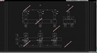
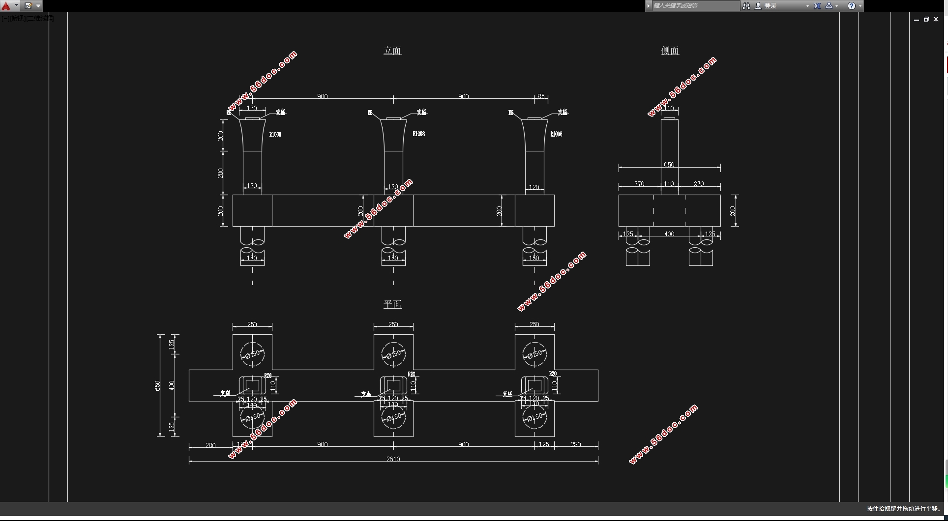
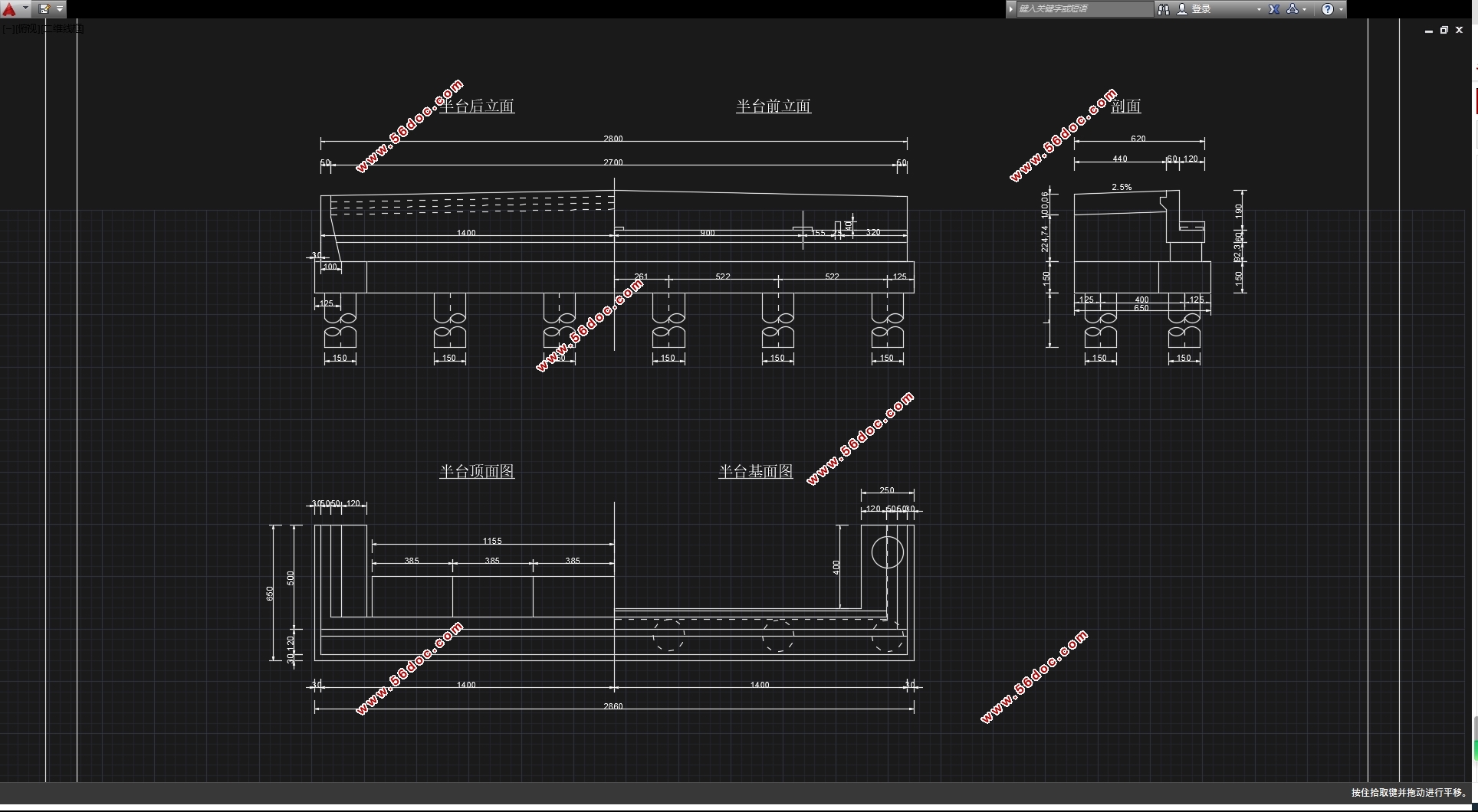
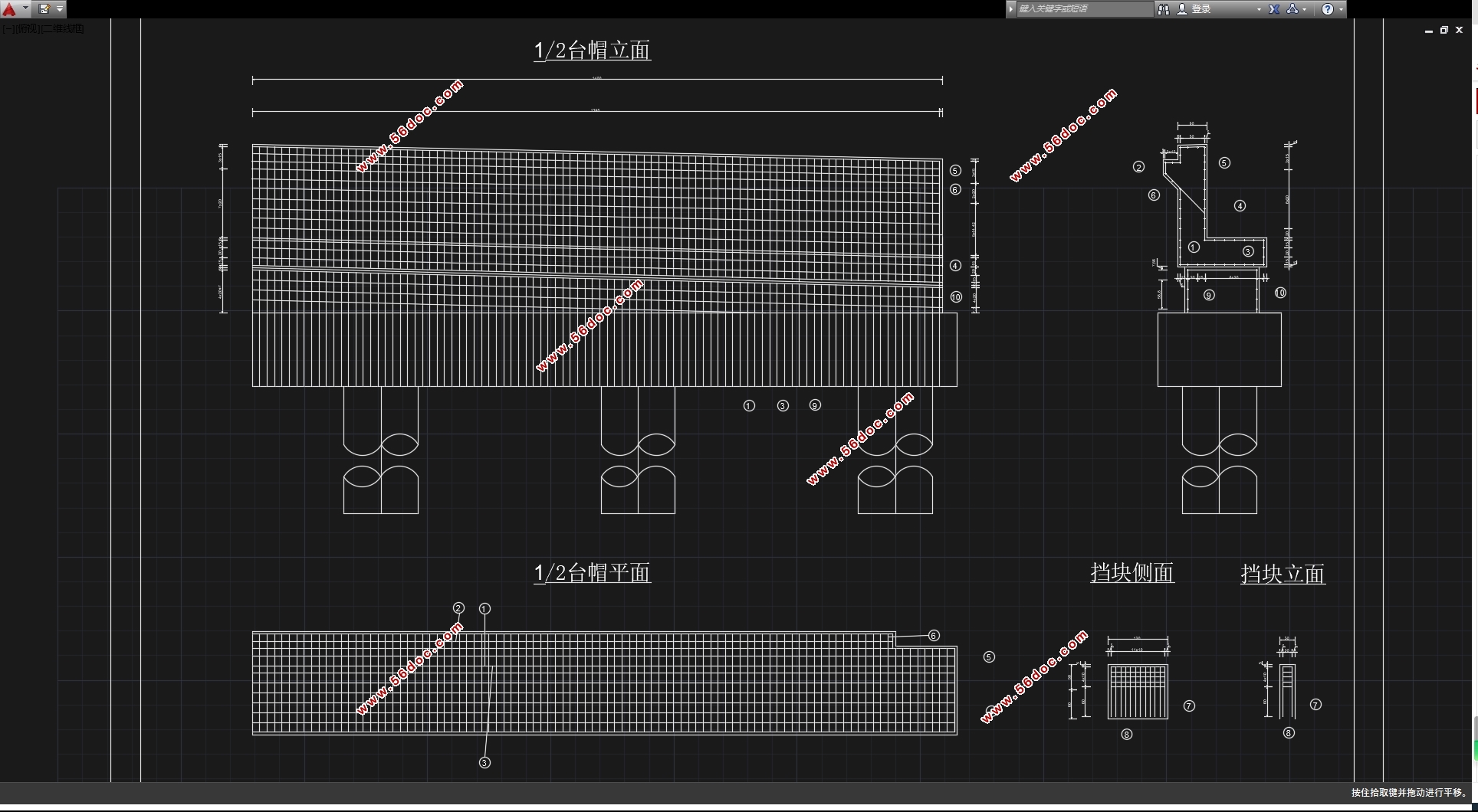
桥梁下部结构设计时,根据支座反力大小选择支座并初步拟定下部结构设计方案,方案确定后再从上到下开始计算。首先是墩(台)帽的计算,通过分析在使用过程中上部构造恒载、盖梁自重以及汽车及防撞墙荷载的作用进行内力计算并进行配筋及承载力校核;其次是桥墩的计算,通过计算所受的恒载、活载进行然后配筋及应力验算;最后是桩基的计算,桩长根据单桩容许承载力的经验公式确定桩长.桩内力的计算采用用m法,根据m法确定的桩的内力进行桩筋的设计及强度验算。
关键词:连续梁桥支反力下部结构
Substructure of Approach Bridge of Huzhou Shijiazhuang Bridge
Abstract
The subject of this design is the design of the lower structure of the (3×30)m continuous beam bridge. The task is mainly divided into two aspects, on the one hand, the support reaction force is calculated based on the existing superstructure drawings, On the other hand, the bearing is selected based on the obtained bearing reaction force and to conduct preliminary design and verification of the substructure.
To reduce the amount of work, we use Midas civil software for superstructure modeling. The prestressed steel bar is configured in consideration of structural self-weight, moving load, phase II, bearing displacement, and temperature influence, and the model is subjected to various types of calculations to obtain support reactions.
In the design of the bridge substructure, the bearing is selected according to the size of the bearing reaction force and a preliminary design of the substructure is planned. After the scheme is determined, the calculation is started from the top down. The first is the calculation of the pier (table) caps. The analysis of the internal forces and the check of the reinforcements and bearing capacity are performed by analyzing the effects of the upper structure dead loads, the self weight of the cap beams, and the load of the automobile and the anti-collision wall during use. Followed by the calculation of the bridge piers, by calculating the dead load, the live load then reinforcement and stress checking. Finally, the calculation of the pile foundation, the length of the pile is determined according to the empirical formula of the allowable bearing capacity of the single pile,.The calculation of the internal force of the pile adopts the m method, and the design and strength of the pile reinforcement are calculated according to the internal force of the pile determined by the m method.
KeyWords:continuous beam bridge; Counter force; Substructure
设计方案说明
工程概况
奚家庄大桥位于浙江湖州经济开发区红丰西路,跨越长湖申航道,是湖州西南分区连接主城干道的重要枢纽。根据规划奚家庄大桥引道落地与二环西路和外庄路平交,红丰西路路幅总宽40m。
工程地质条件
地形、地貌
拟建桥址场地位于湖州市城西南,处于杭嘉湖平原的浙北中部。场地及附近地区河网密布,水系发达,地势地平,属于太湖堆积平原地貌单元。拟建桥梁横跨东苕溪港,水面宽约110m,水深5.50~6.00m,通航。
自然地理概况
本区地处亚热带,气候温暖湿润,四积分明,冬冷夏热。年平均气温15.3℃,多年平均降水量1026毫升,降水的年际和季节变化较大,雨量多集中在六、七、八月份,日照充足,无霜期237天。
场地工程地质条件
场地勘探深度范围内的岩土体按其成因时代不同,划分为9个工程地质层。①层为近期人工填土;②层为全新世冲淤积土;③~⑧层为中、晚更新世粘土、亚粘土、亚粘土混卵砾石、中粗砂含砾石和卵砾石等;⑨层为上侏罗统安山岩类岩石,各工程地质层又据其岩性成分和物理力学性质差异共分为18个亚层。
工程技术标准
1.道路等级:城市次干道
2.设计车速:40公里/小时
3.桥梁设计荷载:公路-I级
4.道路标准断面:3.5m(人行道)+4.5m(非机动车道)+4.5m(绿化带)+15m(机动车道)+4.5m(绿化带)+4.5m(非机动车道)+3.5m(人行道)=40m
5.引桥桥面宽28m,路幅布置为:2.5m(人行道)+3.5m(非机动车道)+16m(机动车道)+3.5m(非机动车道)+2.5m(人行道)
6.桥面铺装:自拟
7.主梁施工方法:自拟
8.支座位移
边支座:下沉5毫米;中支座:下沉5毫米。

目录
摘要 I
Abstract II
第一章 设计方案说明 6
1.1 工程概况 6
1.2 工程地质条件 6
1.2.1 地形、地貌 6
1.2.2 自然地理概况 6
1.2.3 场地工程地质条件 6
1.3 工程技术标准 6
1.4 桥梁总体布置 7
1.5 设计依据 7
第二章 支座反力计算 8
2.1 模型建立 8
2.2 运行分析 8
第三章 支座选用 10
3.1 盆式橡胶支座介绍 10
3.2 选择支座型号并布置 10
3.2.1 支座型号及尺寸 10
3.2.2 支座布置 11
第四章 桥墩墩柱设计 12
4.1 墩柱底截面内力组合 12
4.1.1 竖向力 12
4.1.2 水平力 12
4.2 截面配筋计算 13
4.2.1 按轴心受压构件验算 13
4.2.2 偏心受压构件验算 14
第五章 基础(钻孔灌注桩)设计 15
5.1 荷载计算 15
5.2 桩长计算 15
5.2.1 拟定基桩的桩长和桩径 15
5.2.2 竖向承载力的确定 15
5.3 桩的内力计算 16
5.3.1 桩的计算宽度b 16
5.3.2 桩的变形系数 17
5.3.3 基础变形系数 17
5.3.4 单位力作用在地面处的变位 17
5.3.5 局部冲刷线处桩柱变位计算 17
5.3.6 局部冲刷线以下深度Z处桩身各截面内力计算 17
5.4 桩身截面配筋与承载力验算 19
5.4.1 正截面受压承载力验算 19
5.4.2 按轴心受压构件验算 20
5.5 桩顶水平位移验算 20
5.5.1 桩在地面线处的水平位移和转角( , )的计算 20
第六章 桥台一般构造尺寸的拟定 22
6.1 台帽计算 22
6.1.1 荷载计算 22
6.1.2 内力计算 22
6.1.3 截面验算 24
6.2 4台身计算 25
6.2.1 垂直荷载计算 25
6.2.2 活载对台墙产生的反力 27
6.2.3 水平力计算 27
6.2.4 截面验算 38
6.3 背墙计算 39
6.4 耳墙计算 40
6.4.1 活载等代土层厚度的计算 40
6.4.2 水平土压力计算 41
6.4.3 截面计算 41
致谢 42
参考文献 43
|