泉河大桥5×33m连续梁桥下部结构设计(含CAD图,MIDAS建模)
来源:56doc.com 资料编号:5D28411 资料等级:★★★★★ %E8%B5%84%E6%96%99%E7%BC%96%E5%8F%B7%EF%BC%9A5D28411
资料以网页介绍的为准,下载后不会有水印.资料仅供学习参考之用. 密 保 惠 帮助
资料介绍
泉河大桥5×33m连续梁桥下部结构设计(含CAD图,MIDAS建模)(论文计算书13000字,CAD图10张,MIDAS建模)
摘 要
本次设计为泉河大桥引桥第一联的下部结构设计,上部结构为预应力等高度连续箱梁。本次设计对上部结构进行MIDAS 建模,考虑结构自重、桥面铺装、支座位移、移动荷载及温度影响并配置预应力钢筋,提取支座反力等用于下部结构设计的依据。下部结构的设计依照先拟定后验算的原则,根据相似桥型设计拟定尺寸及钢筋布置,考虑各种状态下的荷载组合,并对墩台进行强度及裂缝验算等。最后,经过适当调整,全部验算结果均符合设计要求,并满足规范标准,则得到最终合理的设计。
关键词:MIDAS建模荷载组合墩台验算
Design of the Lower Structure of 5×33m Continuous Beam Bridge on Quanhe
Abstract
This design is the first part of the substructure design of the bridge, and the upper structure is a skew web prestressed continuous box girder. The design of the design of the upper structure of MIDAS modeling, considering the weight of the structure, bridge deck pavement, support displacement, moving load and temperature influence and configuration of prestressed reinforcement, extraction support back force and other use of the basis for the design of the substructure. The design of the substructure is based on the principle of the first drawing and checking calculation. According to the similar bridge design, the size and reinforcement arrangement are drawn up, the load combination under various states is considered, and the strength and crack checking of the pier are checked. Finally, after proper adjustment, all checking results conform to the design requirements and meet the specifications, and the final and reasonable design is obtained.
Key words: MIDAS modeling;load combination;pier;checking
1.1上部结构工程概况
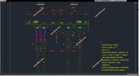
本设计为泉河大桥引桥第一联,桥跨布置为5×33m=165m;全桥采用左右幅分离布置,两幅桥之间空隙2m,单幅桥横向布置为3m(栏杆+人行道)+11.5m(行车道)+0.5m(防撞护栏)=15m,桥梁总宽32m。
上部结构采用斜腹板预应力等高度连续箱梁,箱梁梁高1.8m,采用搭支架逐跨施工。上部结构具体构造由桥型图获得。
1.2工程技术标准
1.道路等级:城市次干道
2.设计车速:40公里/小时
3.桥梁设计荷载:城-A
人群荷载:3.5kN/m
安全等级:一级
4.支座位移
边支座:下沉5毫米;

目录
第一章总体桥型方案 1
1.1上部结构工程概况 1
1.2 工程技术标准 1
1.3 设计规范 1
1.4地质资料. 2
第二章 上部建模与支座选用 6
1.1上部结构建模 6
1.2支座选用与布置 9
第三章 桥墩及基础计算 11
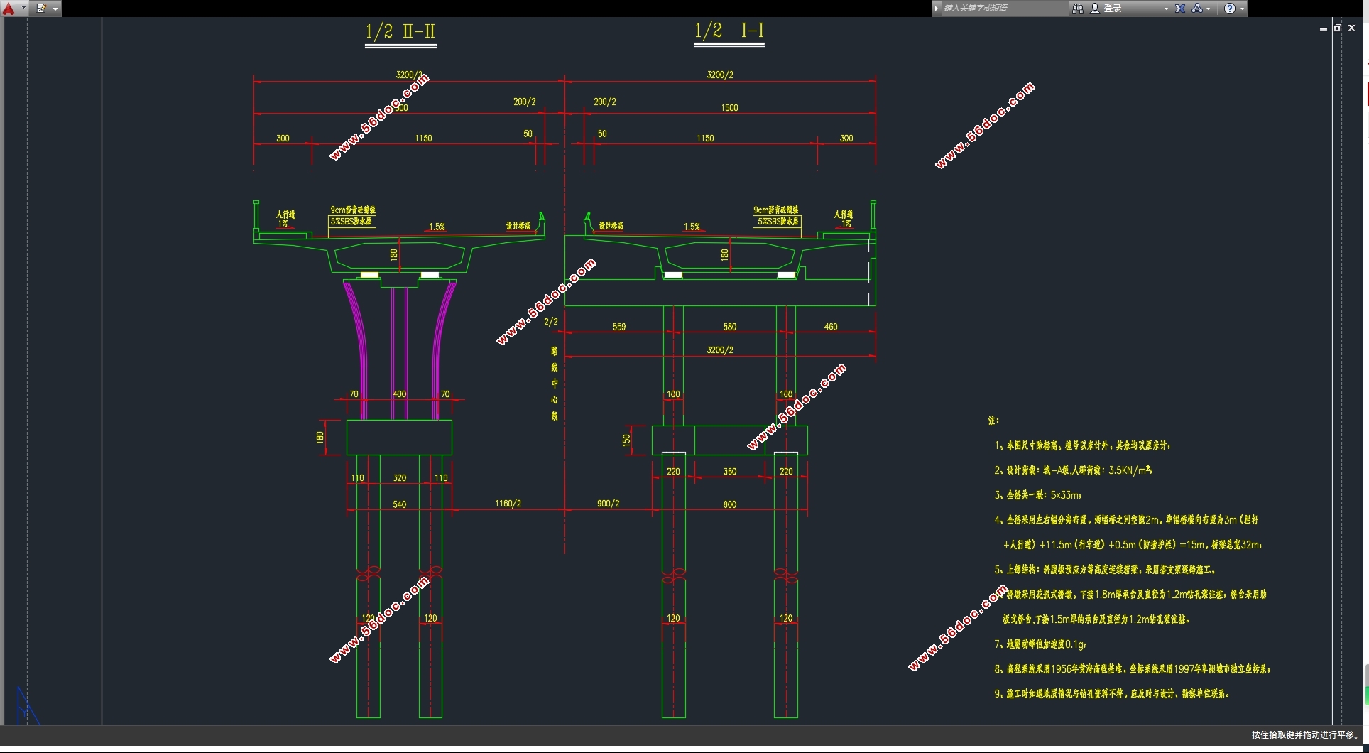
3.1桥墩构造图 11
3.2荷载组合 12
3.2.1上部结构产生的轴力计算 12
3.2.2上部结构产生的弯矩 13
3.2.3制动力 13
3.2.4风荷载 13
3.2.5墩柱弯矩 19
3.2.63#墩强度及抗裂性验算荷载组合 19
3.3桥墩截面安全性验算 20
3.3.1情况1:顺桥向基本组合与正常使用组合验算结果 21
3.3.2情况2:横桥向基本组合与正常使用组合验算结果 23
3.4承台底内力计算 26
3.4.1竖向力 26
3.4.2顺桥向水平力及弯矩 26
3.4.3横桥向水平力及弯矩 27
3.4.4承台底内力 28
3.5桩基验算 33
3.5.1桩基内力验算 33
3.5.2桩基截面验算 37
3.5.3桩基竖向承载力 38
第四章 桥台及基础计算 40
4.1桥台结构构造 40
4.2计算荷载及内力组合 40
4.3台身肋板验算 43
4.4桩基验算 45
4.5桩基竖向承载力计算 50
主要参考文献 53
|