基于BIM的跨铁路转体施工T形刚构桥的施工监控研究(含CAD图)(任务书,开题报告,论文36000字,CAD图9张)
摘 要
随着桥梁施工计算的不断发展,施工监控越来越受到工程师的重视,施工监控技术对于施工质量和成桥状态起着至关重要的作用。本文主要内容包括:
本文首先对T形刚构桥的结构形式、受力特点、适用条件进行了简单的介绍;同时对转体施工工法的工作原理、特点和适用条件进行了简要介绍。
然后本文结合实际工程问题,针对已设计完成的跨铁路T形刚构桥进行设计校核,利用Midas Civil有限元软件进行建模分析,对原设计的合理性进行校核,并根据校核结果提出建议。
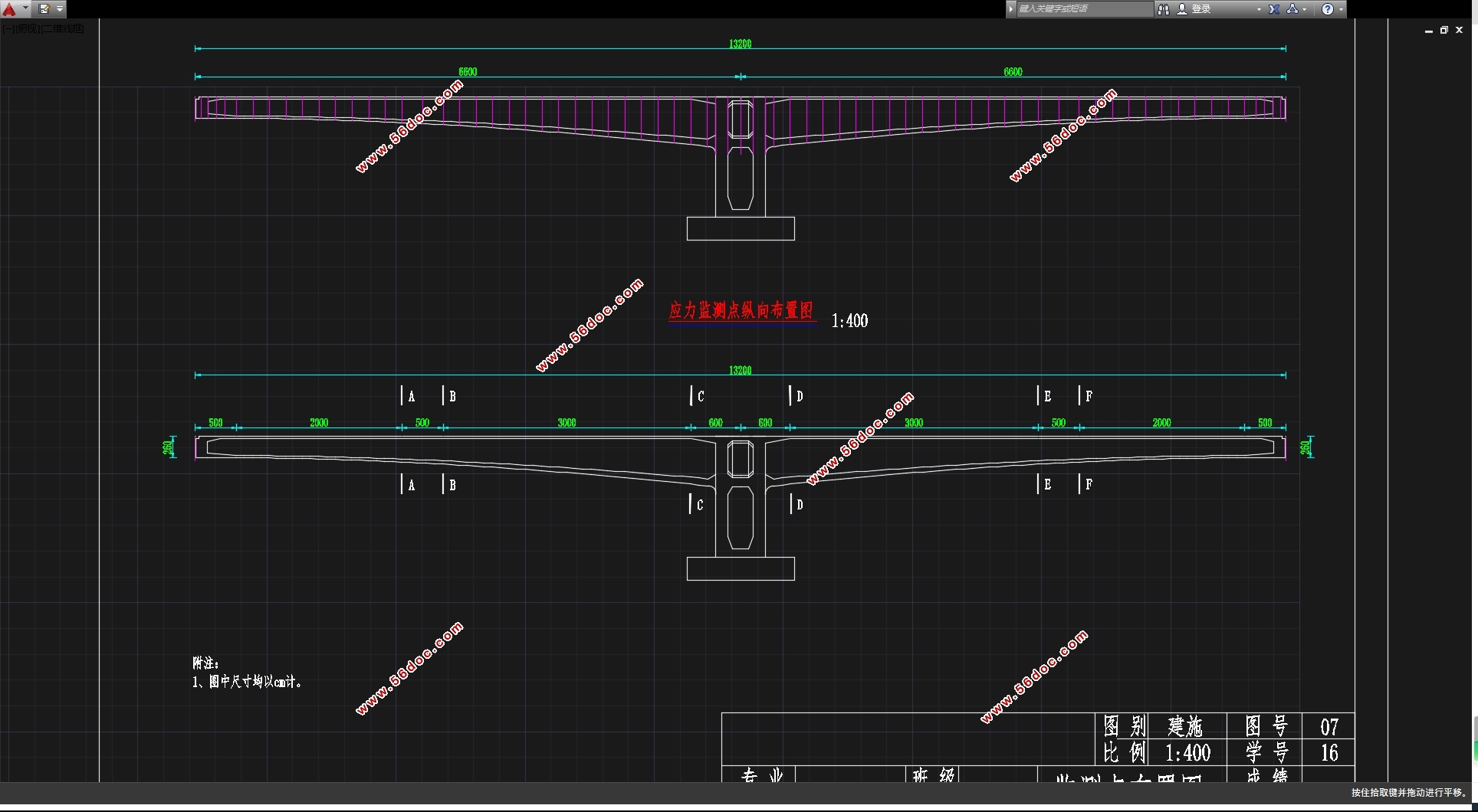
同时,本文对施工监控的原理以及方法进行调研,根据桥梁施工工法与施工步骤编写施工监控报告,确定施工时变形监测节点、应力监测节点以及根据Midas计算结果确定预拱度。
最后,利用Revit软件对T形刚构桥进行三维建模,利用Navisworks根据施工进程对桥梁施工流程进行模拟,对施工流程进行可视化建模,生成施工模拟动画。
关键词:T形刚构 转体施工 施工监控 BIM
Research on Construction Monitoring of T-Shaped Rigid-Frame Bridge Constructed by Trans-Railway Construction Based on BIM
ABSTRACT
With the continuous development of bridge construction calculations, construction monitoring has received more and more attention from engineers. Construction monitoring technology plays a crucial role in construction quality and bridge formation status. The main content of this article includes.
In this paper, the structure, force characteristics and applicable conditions of T-shaped rigid bridges are introduced briefly. At the same time, the working principles, characteristics and applicable conditions of the rotating construction methods are briefly introduced.
Then this paper combines the actual engineering problems, carries on the design check to the cross-rail T-shaped rigid frame bridge that has been designed and designed, uses the Midas Civil finite element software to carry on the modeling analysis, carries on the check to the rationality of the original design, and according to the check result make a suggestion.
This article investigates the principles and methods of construction monitoring, and compiles construction monitoring reports according to the bridge construction method and construction procedures, determines the deformation monitoring nodes, stress monitoring nodes during construction, and determines the pre-camber according to the Midas calculation results.
Finally, using the Revit to three-dimensional modeling T-shaped rigid frame bridge, using Navisworks to simulate the bridge construction process according to the construction process, the visual modeling of the construction process, generate a construction simulation animation.
Key Words:T-shaped rigid bridge; Swivel construction; Construction monitoring; BIM
2.1 桥位自然概况及工程概况
2.1.1地理位置、地形地貌
桥位区位于玉田县中北部,地处燕山南麓山前冲洪积平原上,地势较为平坦,
海拔大部分在 5.8~9.67 米之间。
(1)预应力混凝土转体刚构
跨京哈铁路主桥采用预应力混凝土转体刚构桥,分幅设桥,基础平行铁路方
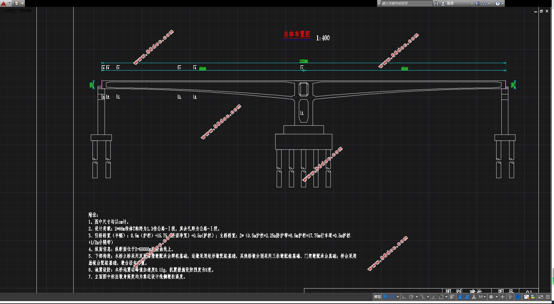
向布置,不侵占铁路路基,桥墩垂直公路路线横断面。孔跨布置为 2×66m,桥面单幅宽 19.5m。转体重量 1.04 万吨(包括外侧护栏),两侧各设有 5m 的支架现浇段。 刚构上部结构采用单箱双室箱形截面,T构中间支点处梁高6.1m,边支点梁高2.6m,梁底线形按1.8次抛物线变化。箱梁顶板宽 19.5m, 两侧悬臂板长各 3.75m,直腹板;悬臂板端部厚20cm,根部厚70cm;箱梁顶板厚30cm;底板厚度为 28cm~110cm;边腹板厚度为 50~90cm;中腹板厚度为 50~90cm。桥面横坡通过箱梁顶、底板旋转而成,顶、底板横坡同桥面,保持腹板沿铅垂方向。

目录
摘 要 I
ABSTRACT III
第一章 绪论 1
1.1 引言 1
1.2 T形刚构桥的构造特点 1
1.3 转体施工的特点 2
1.4 BIM技术在施工中的应用 3
第二章 原设计的校核 5
2.1 桥位自然概况及工程概况 5
2.1.1地理位置、地形地貌 5
2.1.2地层岩性 5
2.1.3地质构造 7
2.1.4水文地质条件 7
2.1.5不良地质及桥位稳定性 7
2.1.6地震 7
2.2主要规范与技术标准 8
2.2.1设计采用主要规范 8
2.2.2设计主要技术标准 8
2.3结构设计说明 9
2.3.1上部结构 9
2.3.2下部结构 11
2.4主要材料 12
2.4.1混凝土 12
2.4.2钢材 13
2.4.3其它材料 13
2.5整体结构检算 13
2.5.1相关计算参数 13
2.5.2模型建立 14
2.5.3短暂状况施工阶段结构检算 15
2.5.4持久状况成桥状态结构检算 20
2.5.5持久状况承载能力极限状态验算 29
2.5.6持久状况正常使用极限状态验算结果 32
2.5.7持久状况构件应力验算结果 34
2.5.8短暂状况构件应力验算结果 38
2.6校核总结及建议 38
2.6.1针对正截面抗裂验算建议 38
2.6.2针对正截面受拉区钢筋拉应力验算建议 39
2.6.3针对短暂状况构件应力验算建议 39
第三章 针对跨铁路转体施工T形刚构桥的施工监控方案 41
3.1施工监控的目的与意义 41
3.2施工监控的依据 42
3.3施工监控的内容 43
3.3.1几何(变形)监控 43
3.3.2应力监控 43
3.3.3稳定控制 44
3.3.4安全监控 45
3.4施工监控的基本原理及方法 45
3.4.1开环控制法 45
3.4.2闭环控制法 47
3.4.3自适应控制法 49
3.4.4最大宽容度法 51
3.5针对此跨铁路T形刚构桥施工监控的具体内容及方法 52
3.5.1施工监控所需资料的收集 53
3.5.2结构有限元仿真分析 53
3.5.3立模标高的确定 58
3.5.4施工支架 59
3.5.5合拢段施工控制 59
3.5.6变形监测 60
3.5.7应力监测 62
3.5.8温度监测 66
3.5.9施工监控预警系统 67
3.6各阶段预拱度的设置 67
3.6.1桥梁主要施工流程及预拱度设置方法 67
3.6.2施工阶段自重作用下预拱度计算 70
3.6.3施工阶段预应力作用下预拱度计算 72
3.6.4施工阶段收缩徐变作用下预拱度计算 74
3.6.5成桥后恒载作用下预拱度计算 76
3.6.6成桥后预应力作用下预拱度计算 79
3.6.7成桥后收缩徐变作用下预拱度计算 81
3.6.8 1/2公路Ⅰ级×1.3活载作用下预拱度计算 83
3.6.9确定最终预拱度 85
第四章 基于BIM的施工流程模拟 87
4.1 Revit软件简要介绍 87
4.2 Revit软件介绍及建模思路 87
4.2.1 建模方式选择 87
4.2.2导入二维图形 89
4.3 Revit建模过程 91
4.3.1轮廓族的建立 91
4.3.2 混凝土梁模型的建立 94
4.3.3 边墩模型的建立 97
4.4 Navisworks软件简要介绍 100
4.5 Navisworks制作施工流程过程 100
4.5.1处理Revit模型并导入Navisworks 100
4.5.2 Navisworks建立Animator动画 102
4.5.3 Navisworks建立TimeLiner施工动画 104
4.5.4导出动画 107
结语 109
致谢 111
参考文献 113
|
