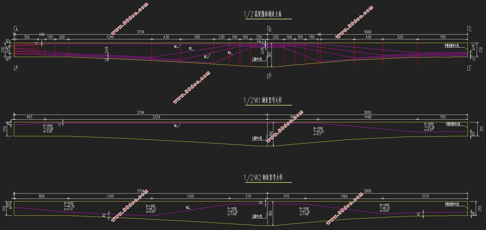
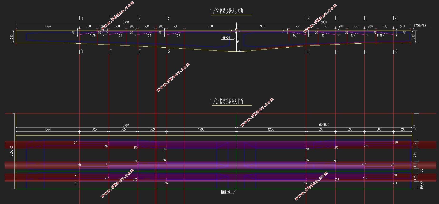
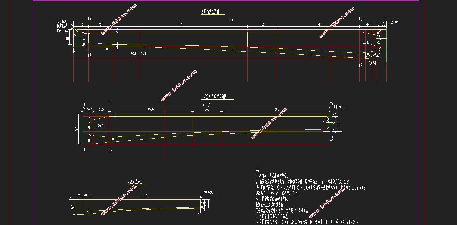
38+60+38m全预应力混凝土连续梁桥设计(含CAD图)(开题报告,计算说明书16000字,CAD图13张)
摘 要
近年来,我国预应力混凝土连续梁桥蓬勃发展。凭借优秀跨越能力、极强适应性、较大的结构刚度、较好的抗地震能力、通车平顺性好以及造型美观等特点,成为了高等级公路上必不可缺的一部分。
本次设计以昆山市中环快速化工程 中环南线为例。对38+60+38m全预应力混凝土连续梁桥进行结构设计。首先参考类似全预应力混凝土连续梁桥进行尺寸初拟。其次采用迈达斯、EXCEL等进行建模、编程计算。考虑桥梁自重、二期荷载、移动荷载和支座位移、温度荷载等引起的次内力,初步确定各种荷载组合作用下的荷载,并对截面预应力筋材料特性、位置形状进行初步设计。最后采用桥梁计算软件迈达斯计算预应力损失并进行承载能力极限状态、正常使用极限状态、持久状况应力的验算(并用手算进行定性校核)。在此基础上对初拟尺寸,对估算钢筋进行微调以达到合理成桥状态。
关键词:结构设计 有限元分析 全预应力连续梁桥 合理成桥状态
Abstract
In recent years,in China,the prestressed concrete continuous girder bridges have developed very fast in the construction of bridges.This kind of bridge has became the irreplaceable part,because of large span,great adaptability to terrain,better structural stiffness,greater earthquake-resistant,less expansion joint and more beautiful appearance.
This paper taken the engineering of urban expressway in Kunshan as example.In this paper,I designed the structure of the 38+60+38m full prestressed concrete continuous girder bridges.
First,searching for some information about full prestressed concrete continuous girder bridges to decide the preliminary dimension.
Second,in this paper,I calculated the combination for short-term action effects with midas,considering dead weight,the action of pavement,traveling load,secondary force of temperature gradient and support displacement,and arrange the form of the prestressed reinforcement preliminarily through excel
Third,with the midas,I checked the limit value of ultimate bearing capacity,normal-using bearing capacity and the stress under the long-term action effect(through the qualitative judgment).Based on these data,adjusting the preliminary dimension and the form of the prestressed reinforcement to achieve better design.
Key words: structural design; full pre-stressed concrete continuous girder bridge ; finite element analysis; reasonable design situation
1.2设计资料
1.汽车荷载等级:公路-I级
2.桥面宽度:
主线高架桥标准宽度为25.5m,横向布置为:0.5m(护栏)+12m(机动车道)+0.5m(中央隔离墩)+12m(机动车道)+0.5m(护栏)=25.5m。衔接匝道位置标准宽度加宽至43.5m,横向布置为:0.5m(护栏)+21m(机动车道)+0.5m(中央隔离墩)+21m(机动车道)+0.5m(护栏)=43.5m。
3.桥面铺装
6cm混凝土调平层+10cm沥青混凝土。
4.主梁施工方法
均采用支架现浇施工
5.支座位移
边支座:下沉5毫米;
中支座:下沉5毫米。


目 录
摘 要 I
Abstract II
第一章 概述 1
1.1 预应力混凝土连续梁桥概述 1
1.2 设计资料 2
1.3 建筑材料选取 3
1.4桥梁结构计算与分析 4
1.5设计采用规范与标准 5
第二章 方案设计 6
2.1 桥梁截面形式 6
2.1.1 桥梁立面 6
2.1.2 主梁截面形式及细部尺寸 6
第三章 内力计算与荷载组合 9
3.1 有限元建模 9
3.2 自重内力计算 11
3.2.1 一期自重 11
3.2.2 二期自重 12
3.3 汽车荷载内力计算 14
3.3.1 相关输入参数说明 14
3.3.2 计算结果 14
3.4 其他内力计算(次内力计算) 19
3.4.1 支座沉降引起的次内力 19
3.4.2 温度引起的次内力 20
3.5 内力组合 22
第四章 预应力钢束的估算和布置 23
4.1 计算原则 24
4.2 材料性能参数 25
4.3 预应力钢筋数量的确定及布置 26
4.3.1 预应力钢筋数量估算 26
4.3.2 预应力钢筋纵断面设计 28
第五章 预应力损失计算 32
5.1摩阻损失σl1 32
5.2锚具变形损失σl2 33
5.3 分批张拉损失σl4 34
5.4 钢束松弛损失σl5 35
5.5混凝土收缩、徐变损失σl6 36
5.6 有效预应力的计算 37
第六章 普通构造钢筋的配置 39
6.1纵向构造钢筋配置 39
6.1.1顶、底板上下面构造钢筋配置 39
6.1.2腹板构造钢筋 39
6.2 构造箍筋配置 40
第七章 承载能力极限状态验算 41
7.1正截面抗弯承载力验算 42
7.2 斜截面抗剪承载力验算 45
第八章 正常使用极限状态验算 47
8.1 正截面抗裂性验算 48
8.2 斜截面抗裂性验算 50
第九章 持久状况应力验算 52
9.1 正截面压应力验算 53
9.2 斜截面主压应力验算 55
9.3 预应力钢束拉应力验算 57
第十章 变形验算 58
10.1 使用阶段挠度计算 58
10.2 预加力引起的反拱计算以及预拱度的设置 59
第十一章 桥墩及桩基设计与计算 60
11.1 桥墩设计 60
11.2 桩的设计方案 61
11.2.1 支座基础设计方案的确定 61
11.2.2 桩根数估算 62
参考文献 63
致谢 64
附录 65
|


