南京2700平米单层轻型门式刚架钢结构工业厂房设计(含建筑图结构图)(任务书,开题报告,外文翻译,论文计算书14000字,CAD建筑图5张,CAD结构图12张)
摘要
本工程为在南京的单层工业厂房建筑结构设计,拟建建筑物总建筑面积为2700平方米。该厂房采用双跨双坡轻型门式刚架体系,跨度为24m和21m,长度为60,柱距为6m。主体结构为一层,内设置10t吊车每跨。梁柱均采用Q235 钢,10.9 级摩擦型高强螺栓连接,焊接采用E43 型焊条,屋面和墙面结构采用压型钢板。
本设计说明书包括建筑设计,结构设计两部分。建筑设计部分具体为建筑平面形式的选择,厂房剖面设计,厂房立面设计,厂房的构造设计,门窗明细表。结构设计部分包括方案选择,吊车梁设计,檩条设计,抗风柱设计,牛腿设计,刚架设计(内力组合),节点设计。各章节都详细演算了主要构件的计算过程。
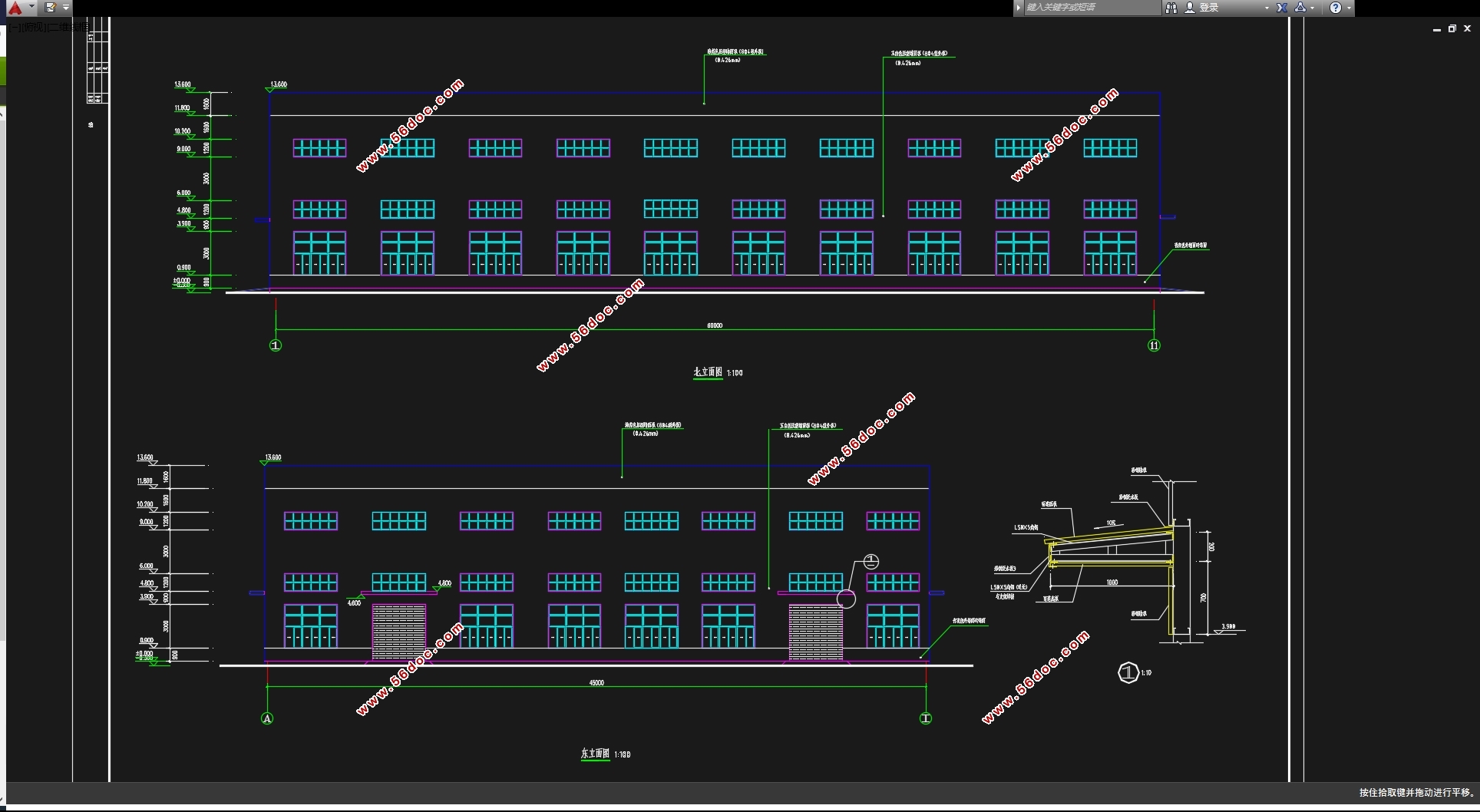
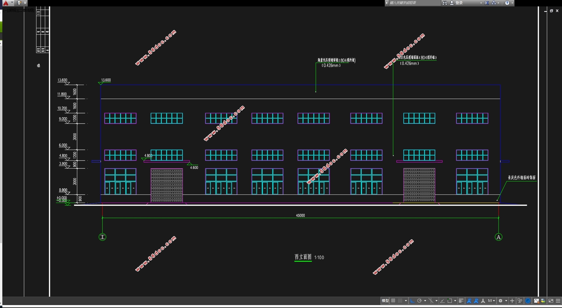
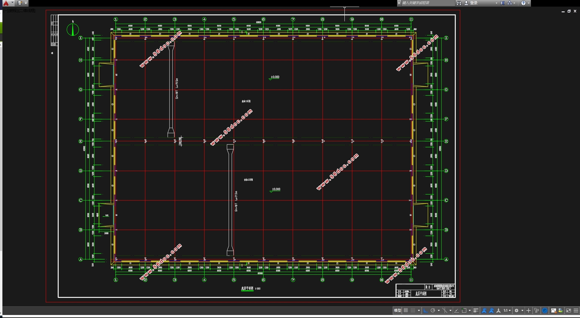
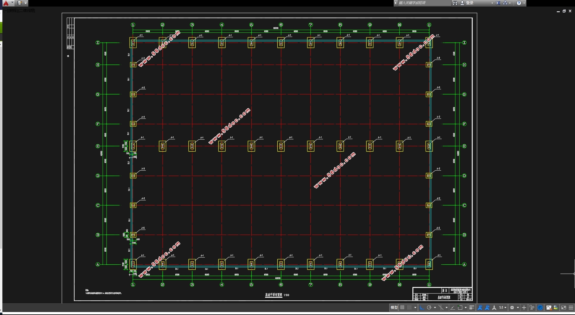
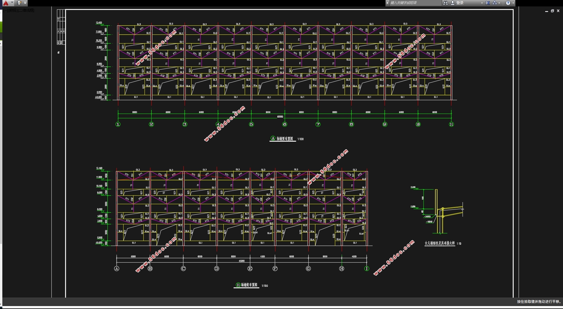
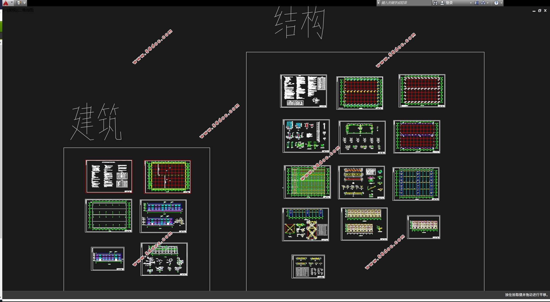
本次设计图纸部分有:厂房平面图,立面剖面及节点详图,刚架施工图,厂房檩条墙梁布置图,吊车梁施工图,支撑布置图,基础平面布置图。
关键词:轻型门式刚架结构,建筑设计,结构设计
Abstract
The single-story industrial workshop design is which located in Nanjing. The total construction area of the project is 2700 square meters. The production workshop is adopted two pairs of cross-slope light portal frame system in the double-storey industrial building. The single span is 24 meters and 21 meters, and it is 60 meters in length. The column space is 6 meters. The main structure has one layer with a 10t crane beam in each span. The steel beam and column are made of Q235.Connection bolts are high strength bolts of friction type with grade 10.9Rod for manual. The type of welding is E43. Rigid connection of column and beam are adopted hinged connections. Architectural design for the construction plane to some of the specific forms of choice, plant profile design, plant design elevation, the structure of plant design, door and window schedules.
Part of the structural design, including program selection, the design of the crane beam, purling design, pillar of wind-resistant design, corbel design, rigid frame design (combination of internal forces), the node design. Chapters detail the main components of calculus calculation.
Part of the design drawings are as follows: plant floor plan, Node elevation profiles and detailed, Frame Construction, wall-beam purlin plant layout map, construction of crane beam map, support layout map, foundation plan.
Key Words: Portal frame light steel,Portal frame,Architectural Design,Structural design.
公司因生产需要建设金加工厂房,采用两跨四坡双脊单层轻型门式刚架钢结构,跨度分别24m和21m,刚架间距6.0m,各跨内设置起重量为10t的A4级电动单梁吊车1台,平面轴线尺寸为60m×45m。

目录
第一章 设计资料 1
1.1工程概况 1
1.2地质资料 2
1.2.1 2
1.2.2 2
1.3 设计内容和要求 3
1.3.1 建筑部分 3
1.3.2 结构部分 3
1.4 毕业设计(论文)图纸内容及张数 4
1.4.1 建筑设计部分 4
1.4.2 结构部分 4
第二章 建筑设计以及结构的选型与布置 6
2.1建筑设计 6
2.1.1 建筑布局 6
2.1.2 主体厂房设计 6
2.1.3 屋面、墙面设计 6
2.1.4 门窗设计 6
2.2结构的选型与布置 6
2.2.1 结构布置 6
2.2.2 结构构件选型 7
2.2.3 基础类型 8
2.2.4 构造说明 8
第三章 结构设计 9
3.1 檩条设计 9
3.1.1 设计资料 9
3.2.2 荷载标准值 9
3.1.3 内力计算 9
3.1.4 截面选择及特性 10
3.1.5 强度验算 12
3.1.6 挠度计算 13
3.2 墙梁设计及拉条设计 13
3.2.1 设计资料与说明 13
3.2.2 荷载及内力计算 13
3.2.3 荷载设计值 13
3.2.4 竖向荷载 14
3.2.5 水平荷载 14
3.2.6 截面参数 14
3.2.7 强度验算 14
3.2.8 挠度验算 14
3.2.9 拉条设计 14
3.3 压型钢板的设计 14
3.3.1 内力计算 15
3.3.2 截面几何特征 15
3.3.3 有效截面计算 16
3.3.4 强度验算 17
3.3.5 刚度验算 18
3.4 吊车梁设计 18
3.4.1 设计资料 18
3.4.2 吊车荷载计算 18
3.4.3 截面选择及几何性质计算 20
3.4.4 吊车梁截面承载力验算 22
第四章 刚架主体设计 27
4.1 刚架荷载计算 27
4.1.1 截面选型 27
4.1.2 荷载计算 28
4.1.3 恒荷载作用下的内力图 29
4.1.4 内力组合 33
4.2刚架梁、柱截面验算 45
4.2.1 刚架梁 45
4.2.2 刚架边柱 52
4.2.3 刚架中柱 57
4.3节点设计 63
4.3.1 中柱 63
4.3.2 左柱 65
4.3.3 梁、梁节点设计 66
4.3.4 牛腿节点设计 68
4.3.4 柱脚设计 70
第五章 基础设计(独立基础) 73
5.1地质资料 73
5.2 柱下独立基础设计 74
5.2.1 确定基础上部荷载 74
5.2.2 确定基础底面积 74
5.2.3 确定基础高度 75
5.2.4基底净反力 75
5.2.5 验算柱边冲切 76
5.2.6 验算台阶处冲切 76
5.2.7基础板底配筋 77
第六章 工程量及简要技术经济分析 78
参考文献 80
致谢 83
|
