镇江某办公大厦给排水设计(含CAD图)
来源:56doc.com 资料编号:5D27453 资料等级:★★★★★ %E8%B5%84%E6%96%99%E7%BC%96%E5%8F%B7%EF%BC%9A5D27453
资料以网页介绍的为准,下载后不会有水印.资料仅供学习参考之用. 密 保 惠 帮助
资料介绍
镇江某办公大厦给排水设计(含CAD图)(任务书,开题报告,外文翻译,计算说明书8000字,CAD图16张)
摘要
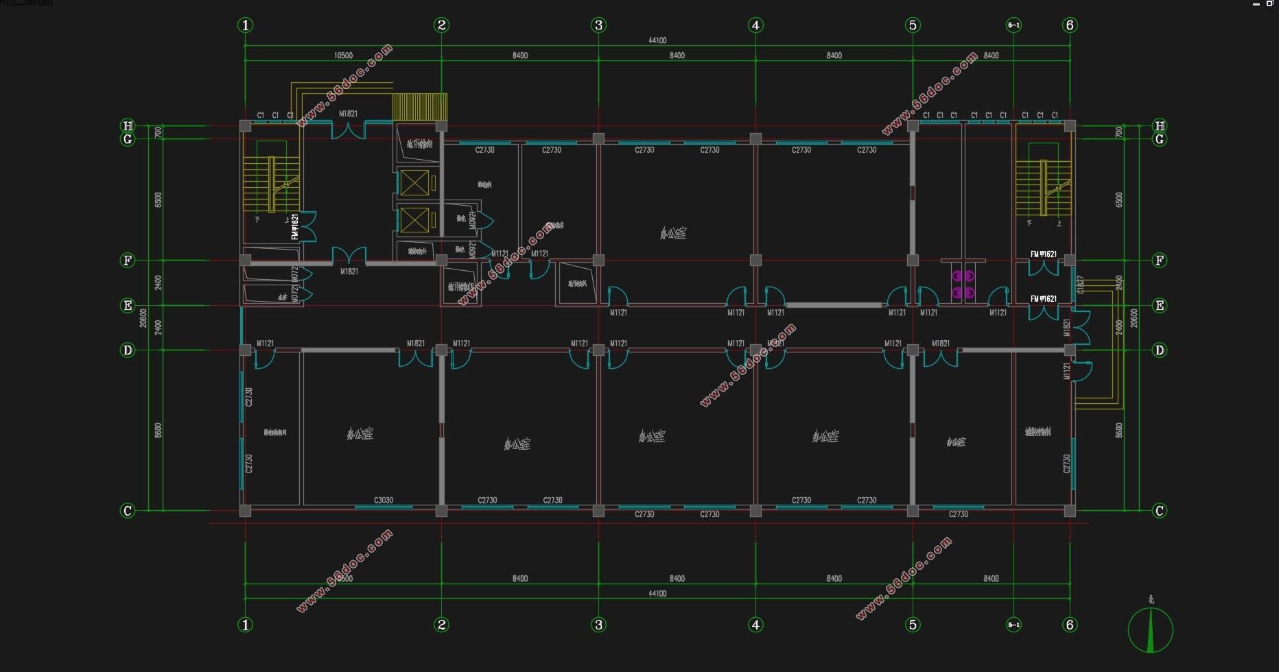
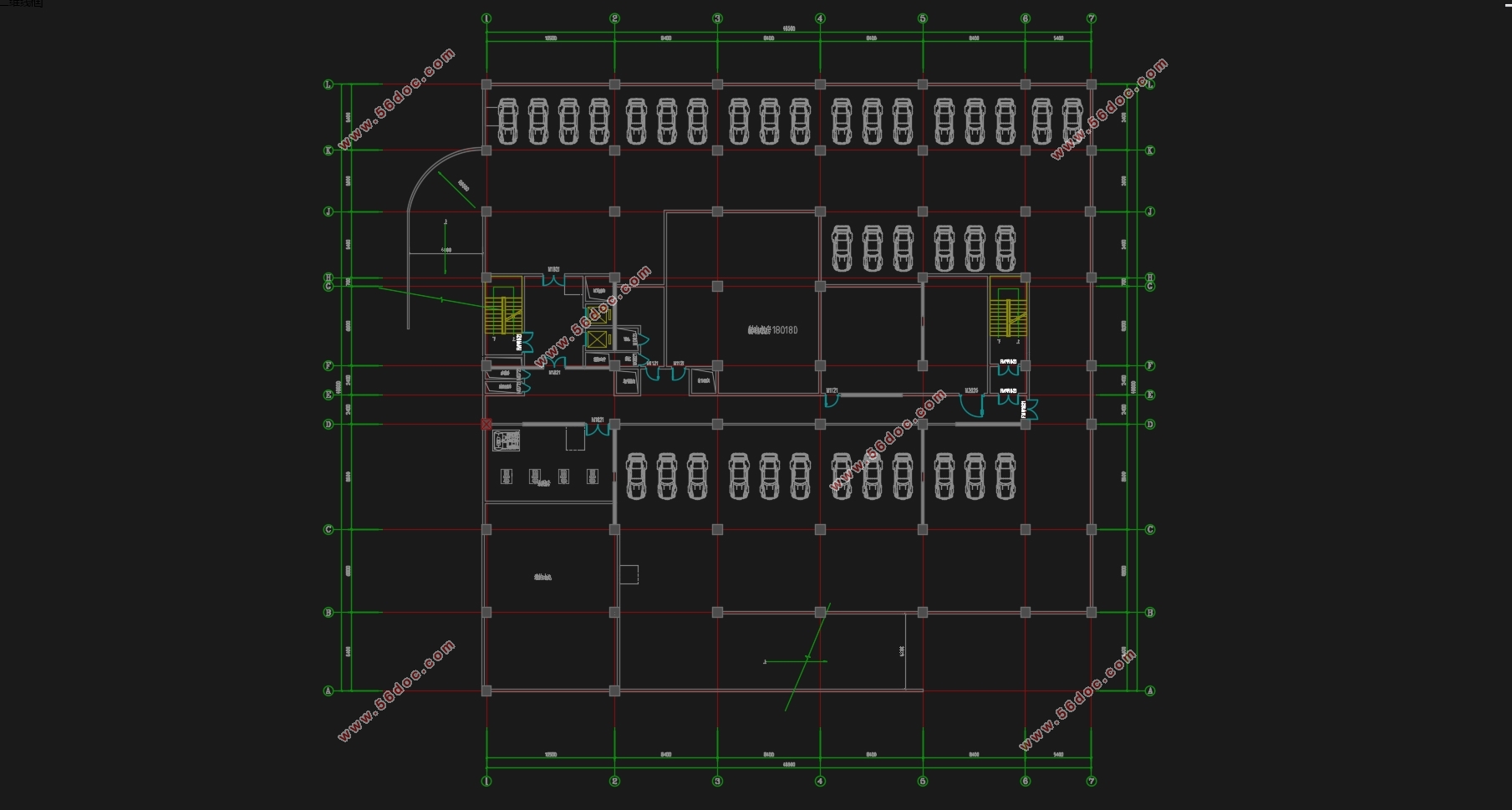
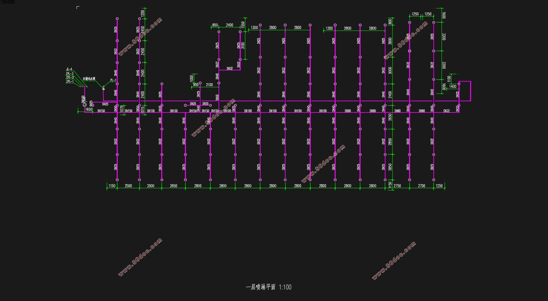
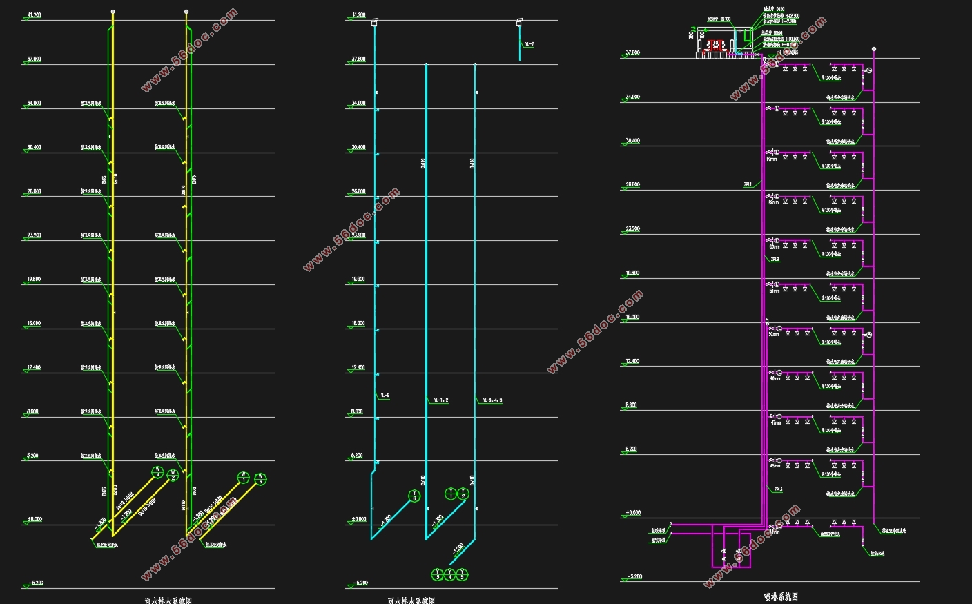
本次设计为镇江市某办公大厦给排水设计,设计内容包括生活给水设计、生活排水设计、消防给水设计、消火栓系统设计、自动喷淋系统设计、雨水排水设计。该建筑为二类高层公共建筑,地上十层,地下一层。地下一层设有泵房,泵房内布置消防水泵和喷淋水泵为消防系统供水,设置无负压供水装置为办公高区供水。办公楼每层有两个卫生间,两个卫生间各设一根立管排水,考虑到卫生间卫生器具较多,每层卫生间均设环形通气管,并在横管起端设置清扫口。雨水使用内排水系统,屋面根据汇水分区设置雨水斗,不上人屋面设置侧墙雨水斗将雨水散排至上人屋面,再由雨水斗收集。
关键词:给水系统排水系统消火栓系统自动喷水灭火系统雨水系统
Abstract
The design is for the water supply and drainage design of Changling Office Building in Zhenjiang City. The design includes life water supply design, living drainage design, fire water supply design, fire hydrant system design, automatic sprinkler system design, and rainwater drainage design. The building is a second-class high-rise public building with ten floors above ground and a basement. There is a pump room on the ground floor, and a fire pump and a spray pump are arranged in the pump room to supply water to the fire protection system. The non-negative pressure water supply device is installed to supply water to the office high area. There are two toilets on each floor of the office building, and one of the two bathrooms is provided with a vertical pipe drainage. Considering that there are more sanitary appliances in the bathroom, each floor of the bathroom is provided with a ring vent pipe, and a cleaning port is arranged at the beginning of the horizontal pipe. The rainwater uses the internal drainage system. The roof is equipped with a rainwater bucket according to the watershed partition. The side wall rainwater bucket is not placed on the roof of the roof to distribute the rainwater to the roof of the upper man, and then collected by the rainwater bucket.
Keyword:Water supply system drainage system fire hydrant system automatic sprinkler system rainwater system
工程概况
本工程位于镇江市,总建筑面积约13900平米,其中:地上建筑面积11700平米,地下2200平米,占地面积1250平米。该建筑为框架—剪力墙结构,地上十层,地下一层,总高度39米,首层高度5.2米,二—十层层高3.6米。
目录
给排水设计 Ⅰ
摘要 Ⅱ
Abstract Ⅲ
设计说明书 1
第一章项目概述 1
1.1 工程概况 1
1.2 设计依据 1
1.3 工程设计内容 1
第二章生活给水系统方案 2
2.1 给水系统方案选择 2
2.2 高区给水方式选择 2
第三章消防系统方案 3
3.1 室内消火栓系统 3
3.2 自动喷淋系统 3
第四章生活排水系统方案 5
4.1 排水系统方案选择 5
4.2 排水通气系统 5
第五章雨水排水系统方案 6
5.1 雨水排水系统方案选择 6
设计计算书 7
第六章生活给水系统计算 7
6.1 用水定额及用水量 7
6.2 设计秒流量 7
6.3 给水系统水力计算 7
6.3.1 各卫生器具详情 7
6.3.2 高区部分水力计算 8
6.3.3 低区市政给水部分水力计算 9
6.4 市政直供部分所需压力校核 12
6.5 高区设备选型与所需压力校核 12
6.5.1 高区给水系统所需压力 12
6.5.2 设备选型 13
6.5.3减压阀设置 13
第七章消火栓系统计算 15
7.1 消火栓的布置 15
7.2 消火栓的水压 15
7.3 消火栓系统水力计算 17
7.4 消火栓系统减压计算 18
7.5 消防箱配置 19
7.6 消防水池 19
7.7 屋顶消防水箱 20
第八章自动喷淋系统计算 21
8.1 系统的设计流量 21
8.2 水力计算(作用面积法) 22
8.3 增压与贮水设备 26
8.4 喷淋减压孔板计算 26
第九章生活排水系统计算 28
9.1 设计秒流量 28
9.2 出户管计算 29
第十章雨水排水系统计算 30
10.1 设计秒流量 30
10.2 立管管管径 31
参考文献 33
|
