常州绿建办公大楼给排水工程设计(含CAD图)(任务书,开题报告,外文翻译,计算说明书17000字,CAD图21张)
摘 要
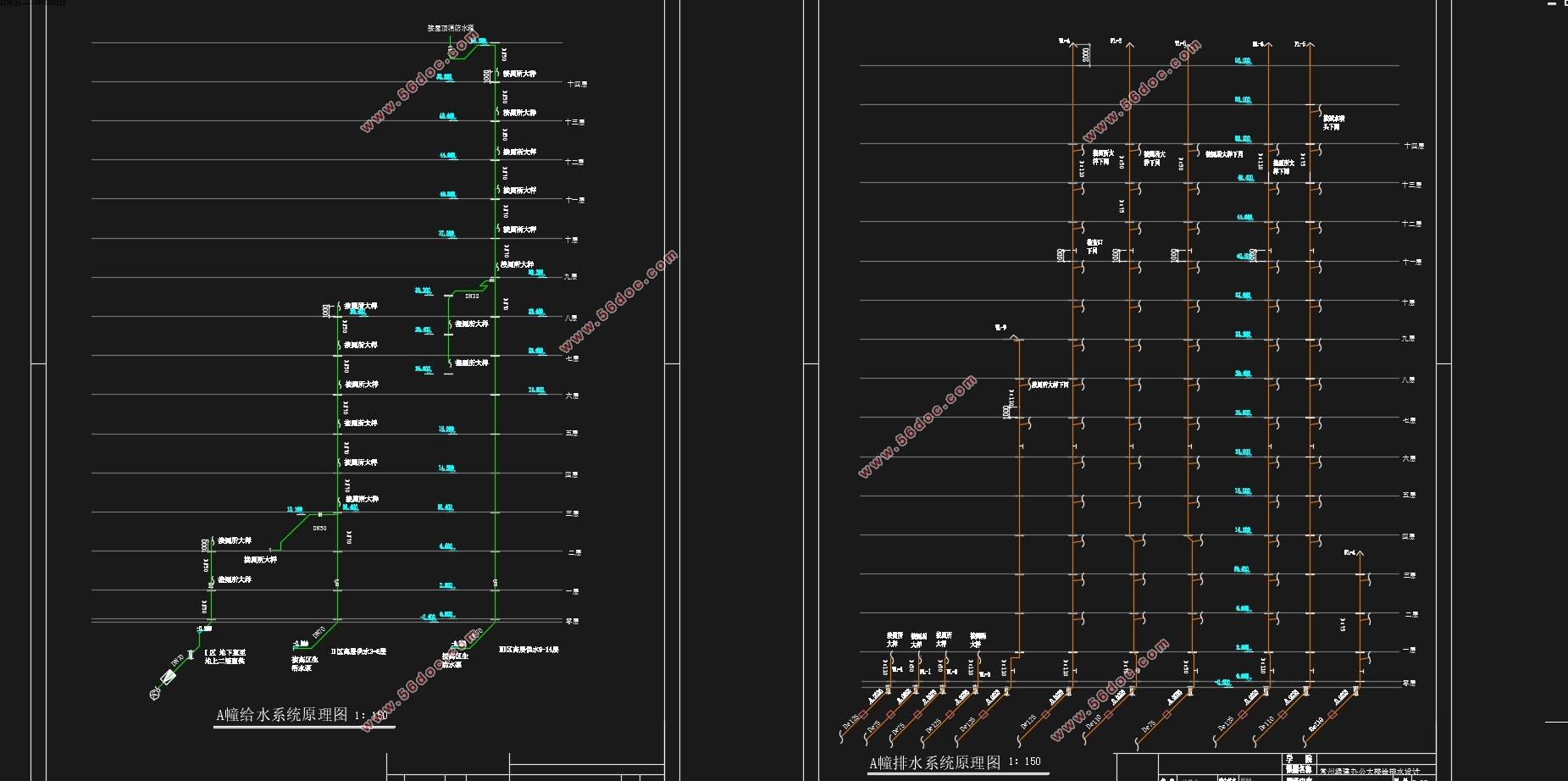
本设计地下一层至地上二层为市政管网直供,三至十四层为水泵水箱联合供水的给水方式。直供部分从市政给水管网接一根DN70的引入管,另一根DN100的引入管接至地下一层生活水池和消防水池。生活水池为砖砌混凝土结构,消防水池采用砖砌混凝土结构,设置在地下室水泵房。排水采用生活污、废水分流制,通气管均采用伸顶通气立管通气。泵房排水沟经汇集排至地下一层集水井,经潜污泵提升排至检查井后直接排入市政污水管网。建筑地上的生活污水通过排水立管在地下室屋顶排到室外。屋面雨水经屋面雨水斗收集后由雨水管排至地面经雨水井汇集排至市政雨水管网。
根据规范,该建筑为一类建筑,属中度危险一级。室内消防流量40L/s。充实水柱取13m,水龙带长度取25m,水枪喷嘴流量5.3L/s,消防立管管径为DN100。在顶层消防电梯间设试验消火栓一个,每个室内消火栓箱内均设有远距离启动消防泵的按钮。
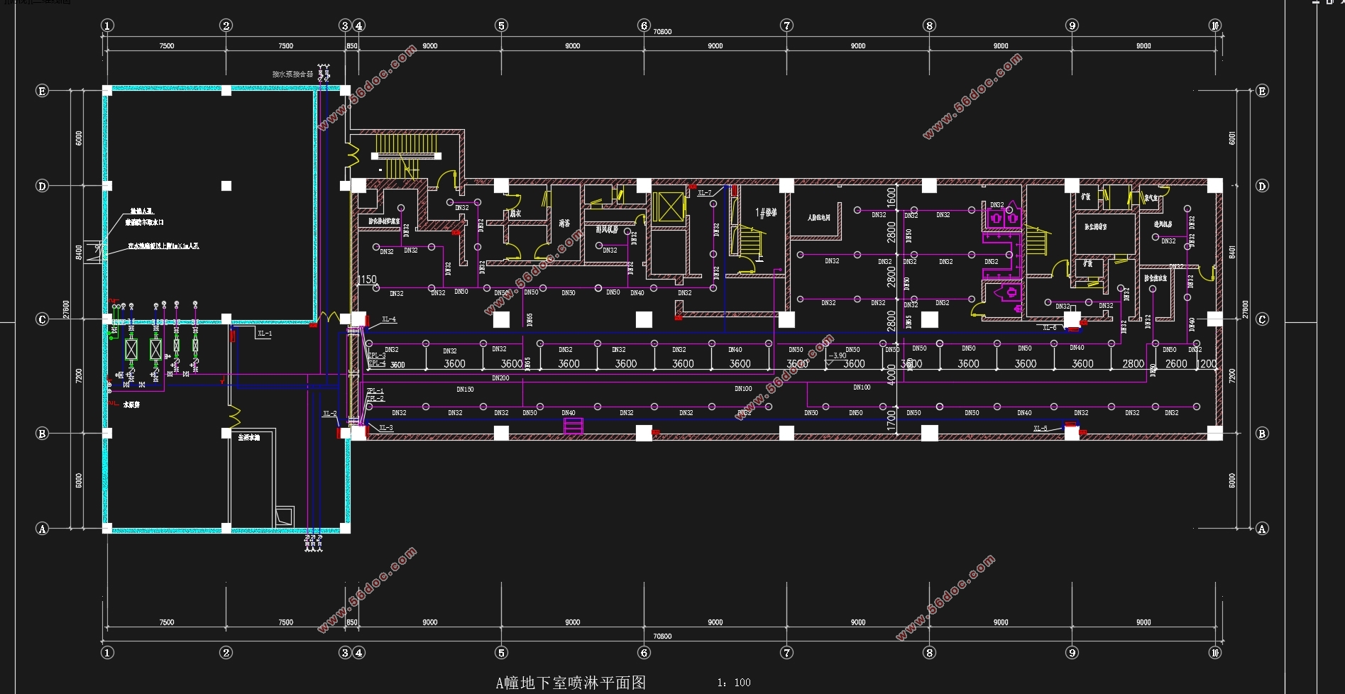
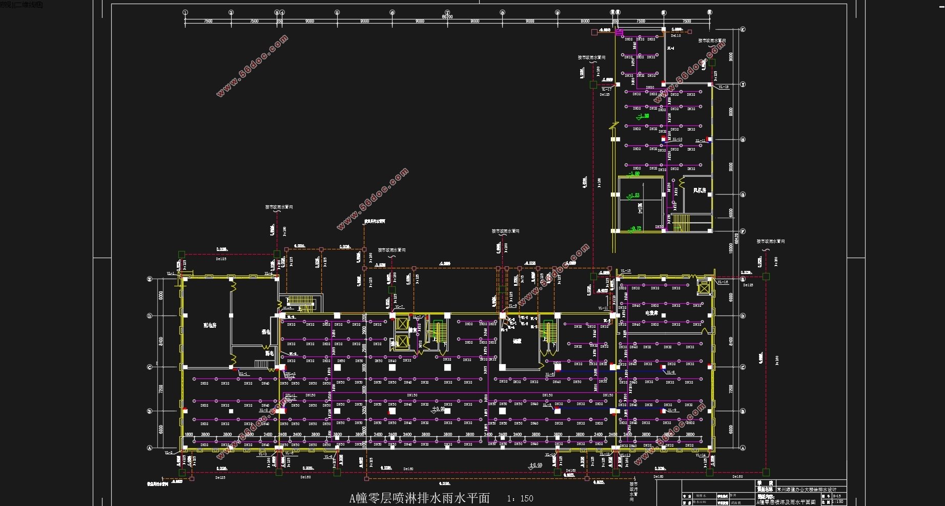
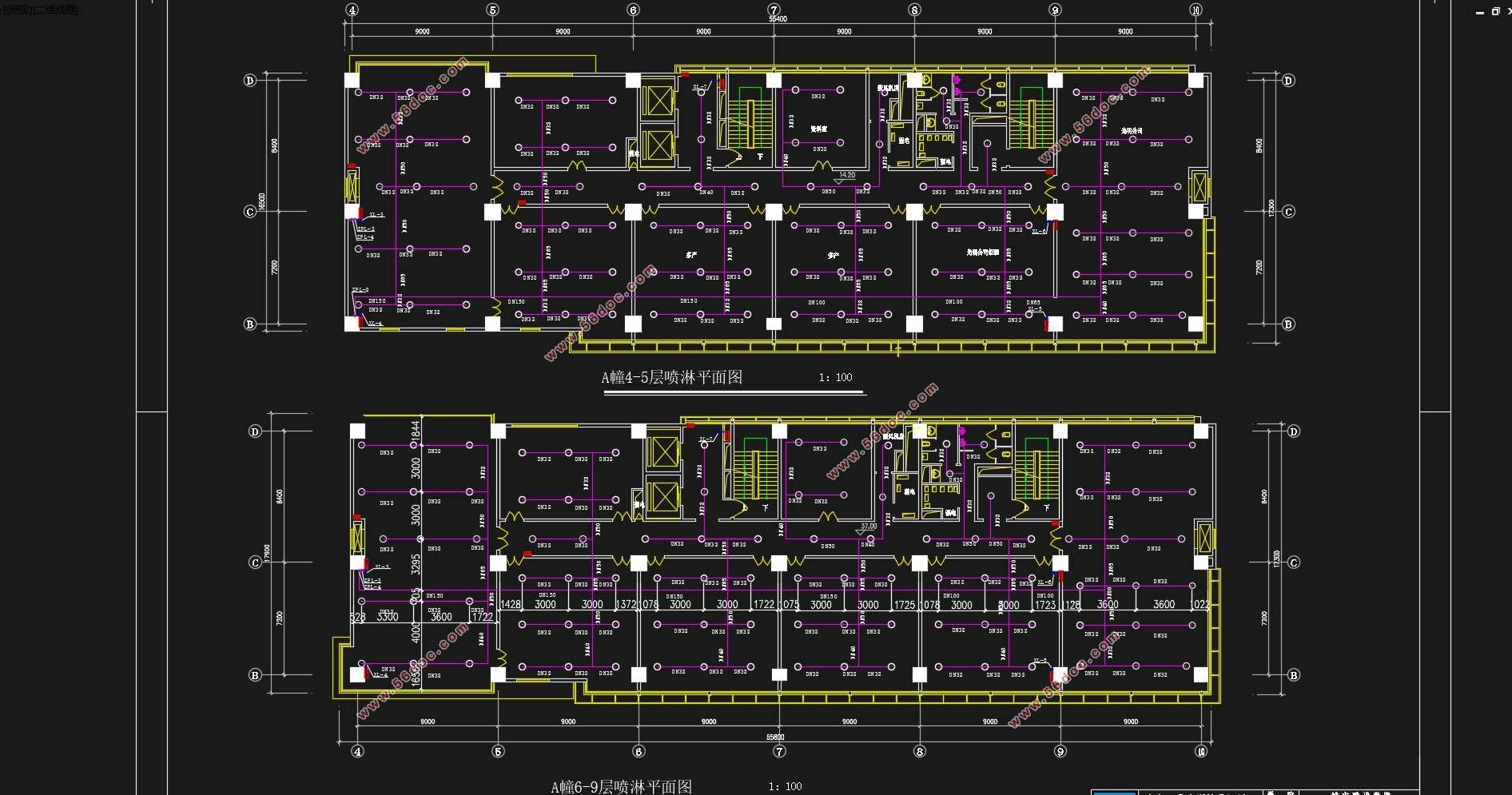
该建筑采用湿式自动喷淋灭火系统,报警阀设于地下一层,各层均设水流指示器和信号阀,其信号均送入消防控制中心进行处理。各层均采用自动喷淋系统,地下一层采用下垂式喷头。各层均设末端试压装置。本工程的自动喷水灭火系统分4个区。屋顶水箱为36立方米,是消防喷淋合用水箱,贮存有10min自动喷水灭火系统、室内消火栓系统用水量。自动喷水灭火系统和消火栓系统的初期灭火由水箱供水,后期供水由地下室的消防水泵和自喷泵供水,各支管与立管连接处设置减压孔板。
根据重力式雨水系统和虹吸式雨水系统的设计分析及造价对比后,本设计采用重力式雨水系统。
关键词:给水系统 排水系统 消火栓系统 自动喷水灭火系统 雨水系统
Abstract
The design of the basement to the ground floor of the municipal pipe network directsupply three to ten four for the joint water pump water tank water supply way.
Supplying part from the municipal water supply network connected to an introduction pipe DN70, DN100 introduced into the other tube is connected to the ground floor living pond and fire pond. Living Pool brick concrete structure, fire water usingconcrete masonry structure, set up in the basement pump room. Using domestic sewage drainage, waste water diversion system, are used snorkel stretch top vent risers ventilation. Pumping stations to drain through pooled row basement sump, the submersible sewage pump upgrade directly into the rear discharge to municipal sewer manholes. Construction of sewage on the ground through the drain standpipe in the basement of the roof outside. After the roof rainwater collected from the roof waterbucket rain water pipe to discharge ground water wells pooled by row to themunicipal storm sewer system.
According to the specification, the building is a building type, is a moderate risk level. Indoor fire flow 40L / s. Take enrich the water column 13m, hose lengths are 25m, gun nozzle flow 5.3L / s, fire standpipe diameter is DN100. Elevator on the top floor fire hydrant provided a test for each fire hydrant box fire pumps are equipped with remote start button.
The building wet automatic sprinkler system, alarm valve located in the basement, the layers are set to flow indicator and signal valve, which signals are sent to the fire control center for processing. The layers are made of automatic sprinkler system, the use of the basement drooping head. The layers are set end pressure test apparatus. Automatic sprinkler system of the present project is divided into 4 zones. Roof water tanks of 36 cubic meters, is combined fire sprinkler water tank, storage has 10min sprinkler systems, fire hydrant system water. Automatic sprinkler system and fire hydrant system initial water from the tank, the water in the basement of the late fire pumps and pump water from the spray, pipe and riser connections each branch set up by the pressure plate.
According to post-design analysis and comparison of cost and gravity drainage systems Siphon rainwater system, the design uses gravity drainage systems.
Key words: water supply system, drainage system fire hydrant system sprinkler systems Rainwater system.
3.1设计说明
根据《高层建筑民用防火规范》(下称《高规》)本建筑为一类建筑,一类高层建筑的耐火等级应为一级,设计内容包括室内消火栓系统。此建筑对消防的要求较高,必须保证消防的安全可靠,室内消火栓给水系统采用独立的消防给水系统,按《高规》要求,采用两股水柱,每股流量 ,消火栓保护半径为24米。
消火栓宜布置在明显,易于取用的地方。消火栓的布置范围包括全部各楼层、消防电梯前室和屋顶检验用。
室外消防管网宜布置成环状,分别在地下一层和顶层成环。
3.2设计参数
1.消防用水量标准
①室内消防用水量40L/s。每根竖管最小流量为15 L/s,每支水枪最小流量为5 L/s。
②火灾延续时间为3h。
3.3系统设计
1.消火栓系统组成
由消防水池、消防栓系统水泵、消防立管、消火栓、水泵结合器等组成。消火栓给水方式:
①10min前,由屋顶水箱供水。
②10min后,消防水箱—消防栓系统水泵—消防立管—消火栓。
2.室内消火栓系统
室内消火栓系统为常高压系统。系统消防水泵—屋顶消防水箱联合供水。
3.消火栓给水管道的安装与布置
(1).消火栓给水管道的安装与生活给水管道基本相同。
(2).管材采用内外壁热镀锌钢无缝钢管。
(3).为了使每层消火栓的出水流量接近设计值,在栓口静压超过0.5MPa的消火栓前设置减压孔板。
(4).消火栓采用减压稳压型消火栓,内设DN65,衬胶麻质水龙带25米,¢19水枪一支,指示灯一支,消防水泵启动按钮一只。消火栓采用单出口,栓口离地高度为1.1m。
(5).消防给水管上的阀门,闸阀采用Z41H-10型闸阀,阀门常开,只有管道检修时才允许关闭。

计算书目录
摘 要 2
Abstract 3
第一章 设计说明书 7
一、建筑给水系统设计 7
1.1给水系统的选择 7
1.2室内给水系统的组成 8
1.3给水管道的布置与敷设 8
二、建筑排水系统设计 9
2.1排水方式选择 9
2.2通气管选择 9
2.3 排水系统的组成 9
2.4排水管道及设备安装要求 9
2.5 关于清扫口、检查口 10
三、建筑消火栓系统设计 11
3.1设计说明 11
3.2设计参数 11
3.3系统设计 12
3.消火栓给水管道的安装与布置 12
四、建筑自动喷水灭火系统 12
4.1设计说明 12
4.2基本设计数据 13
4.2.1喷头选择与布置 13
五、建筑雨水排水系统 13
5.1雨水排水系统的选择 13
5.2雨水排水系统的组成 13
5.3雨水管道的敷设与布置 13
第二章 设计计算书 14
一、给水系统 14
1.1室内给水系统的计算 14
1.1.1给水用水定额 及时变化系数 14
1.1.2.最高日用水量 计算 14
1.1.3.最高日最大时用水量 计算 14
1.1.4.生活水池的容积计算 14
1.2给水管网水力计算 15
1.2.1给水管道设计秒流量 计算 15
1.2.2.给水系统所需水压计算 15
1.2.3.给水水力计算 16
二、排水系统水力计算 23
2.1确定排水体制 23
2.2水力计算 23
2.3排水立管管径的确定 24
2.4排水横管管径的确定 28
2.5 集水井容积的计算 31
三、消防系统计算 31
3.1消火栓系统计算 31
3.1.1消防水池的设置 32
3.1.2 体积计算 32
3.2 屋顶消防水箱 33
3.2.1水箱体积 33
3.3 消火栓布置 33
3.3.1消火栓布置规范 33
3.4 消火栓水力计算 34
3.4.1消火栓、水带、水枪型号的选择 34
3.4.2最不利点消火栓所需要的压力和实际射流量 34
3.4.3消防管网水力计算 35
3.4.4消防水箱设置高度的校核 38
3.4.5局部增压设备的计算与选择 39
3.4.6消防水泵的选择 39
3.4.7 减压孔板计算 40
3.4.8 水泵接合器设置 44
四、自喷系统计算 44
4.1喷淋布置 44
4.2喷淋管线布置 44
4.3自喷计算 45
4.3.1各报警阀组最不利层的喷淋水力计算 45
4.4 喷淋系统水泵选择 51
4.5减压计算 52
五、雨水系统计算 54
5.1汇水面积计算 54
5.2雨水量计算 57
5.3雨水斗选用 58
5.4连接管计算 58
5.5悬吊管计算 58
5.6立管计算 59
5.7排出管计算 59
参考文献 60
|
