A市排水工程初步设计(含CAD图)
来源:56doc.com 资料编号:5D27483 资料等级:★★★★★ %E8%B5%84%E6%96%99%E7%BC%96%E5%8F%B7%EF%BC%9A5D27483
资料以网页介绍的为准,下载后不会有水印.资料仅供学习参考之用. 密 保 惠 帮助
资料介绍
A市排水工程初步设计(含CAD图)(任务书,开题报告,外文翻译,计算说明书13000字,CAD图23张)
摘要
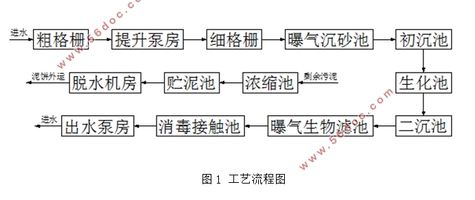
本设计需要根据给定的原始资料及相关要求,进行完整的A市排水工程初步设计。经过经济效益、环境效益和社会效益等方面的考虑,排水管网采用完全分流制排水系统。污水雨水均自流排除,依据地形特点最近最快排入水体。污水处理厂根据进水各指标浓度以及一级排放标准的要求,选择完整的二级处理系统。工艺流程包括污水的物理处理阶段、生物处理阶段和污泥处理阶段。
污水的物理处理阶段构筑物包括:格栅、污水提升泵站、曝气沉砂池和初沉池。紧接着的生物处理阶段包括厌氧-缺氧-好氧生物反应池和曝气生物滤池。曝气生物滤池出水进入消毒接触池,进一步处理后达到国家排放一级A标准,经出水泵房进行回用或排放。设计中初沉污泥和活性污泥混合后依次进入浓缩池,贮泥池和脱水机房。
关键词:管网;污水处理厂;AAO;曝气生物滤池;活性污泥
A preliminary design of the Urban Drainage Project
Abstract
According to the given raw data and requirements,this design needs to complete a preliminary drainage design of the A city.Take a consideration of economic benefits、environmental benefits and social benefits,we choose the completely separate system of drainage system.Polluted water and rainwater all gravity excluded,and they flow into the water bodies according to the topographical features.According to the influent concentration indexes and the emission standards,we select the complete secondary treatment system finally.The process comprising physical treatment stage of sewage、stage biological treatment of sewage and sludge treatment stage.
Physical treatment phase structures of sewage comprising grill、sewage pump stations、aerated grit chamber and primary sedimentation tank.Followed biological treatment stage comprising AAO bioreactor and BAF.The water of BAF flow into the contact tank disinfection,aim to meet the national emission standards of A.Then,water shall be reuse or discharge with the help of the water pumping station.In the design,sludge and activated sludge have been mixed first,and then flow into thickener、sludge storage tank and dehydration room one by one.
Key Words:Pipe Network;Sewage treatment plant;AAO;BAF;Activated Sludge
1.1 设计题目
根据给定的原始资料,参考规范及市政规划部门设计要求,进行A市排水工程初步设计。
1.2 设计任务
1.2.1 排水系统设计
①按照完全分流制进行排水系统设计,进行雨、污管渠的布置;
②进行排水管道设计流量的计算,排水管道的水力计算(包括管段长度、设计流量、管径、设计坡度、设计充满度、流速、埋深等);
③绘制排水管网系统总平面设计图;绘制排水主干管的纵剖面图。
目 录
摘要 1
Abstract 2
一、设计概述 5
1.1 设计题目 5
1.2 设计任务 5
1.2.1 排水系统设计 5
1.2.2 污水处理厂设计 5
1.3 设计阶段 5
1.4 设计依据 5
1.5 设计原始资料 6
1.5.1 城区规划情况 6
1.5.2 气象条件 6
1.5.3 城区给排水现状 7
1.5.4 城区混合污水水质情况 8
1.5.5 污水处理厂处理程度及污水回用要求 8
1.6 设计提交成果 8
二、工程设计说明 9
2.1 居住区资料 9
2.2 污水处理系统的选择 9
2.3 污水管道系统设计 9
2.3.1 排水方式及布置方式的确定 10
2.3.2 污水管段定线 10
2.4 雨水管道系统设计 10
2.5 污水厂设计 10
2.5.1 污水处理厂的布置 10
2.5.2 污水处理方法的选择 11
三、 排水管网部分 12
3.1 污水管网 12
3.1.1 污水管网水力计算步骤 12
3.1.2 污水管网设计计算 12
3.1.3 设计流量计算 12
3.2 雨水管网 13
3.2.1 雨水管网水力计算步骤 14
3.2.2 雨水管网设计计算 14
四、 污水处理厂的计算 15
4.1 粗格栅 15
4.2 集水井和提升泵房 16
4.3.1 集水井 17
4.3.2 提升泵房 17
4.3 细格栅 18
4.4 曝气沉砂池 19
4.4.1 沉砂池计算 20
4.4.2 沉砂池供气量计算 22
4.5 配水井 22
4.6 辐流式初沉池 23
4.7 生物反应池 24
4.7.1 设计依据 24
4.7.2 设计参数 25
4.7.3 设计计算 26
4.8 化学除磷 34
4.9 辐流式二沉池 34
4.10 曝气生物滤池 36
4.11 消毒接触池 41
4.12 中水池 42
4.13 出水泵房 42
4.14 重力浓缩池 43
4.15 贮泥池 44
4.16 污泥脱水 45
4.17 鼓风机房 47
参考文献 48
致谢 49
|
