14万m3/d给水工程设计(含CAD图)(任务书,开题报告,计算说明书52000字,CAD图9张)
摘 要
随着经济的快速发展和城市化进程加快,越来越多的地表水源受到有机污染,水中氨氮、生化需氧量、高锰酸盐指数等指标超过《地表水环境质量标准》(GB3838-2002)Ⅲ类,常规工艺处理不能达到《生活饮用水卫生标准》(GB 5749-2006)的要求,给饮用水安全造成威胁,因此微污染水源水处理成为人们关注的热点。
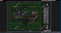
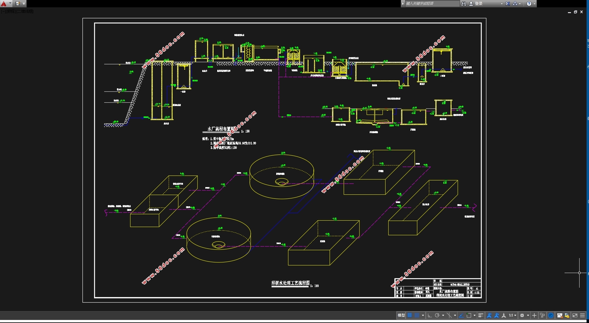
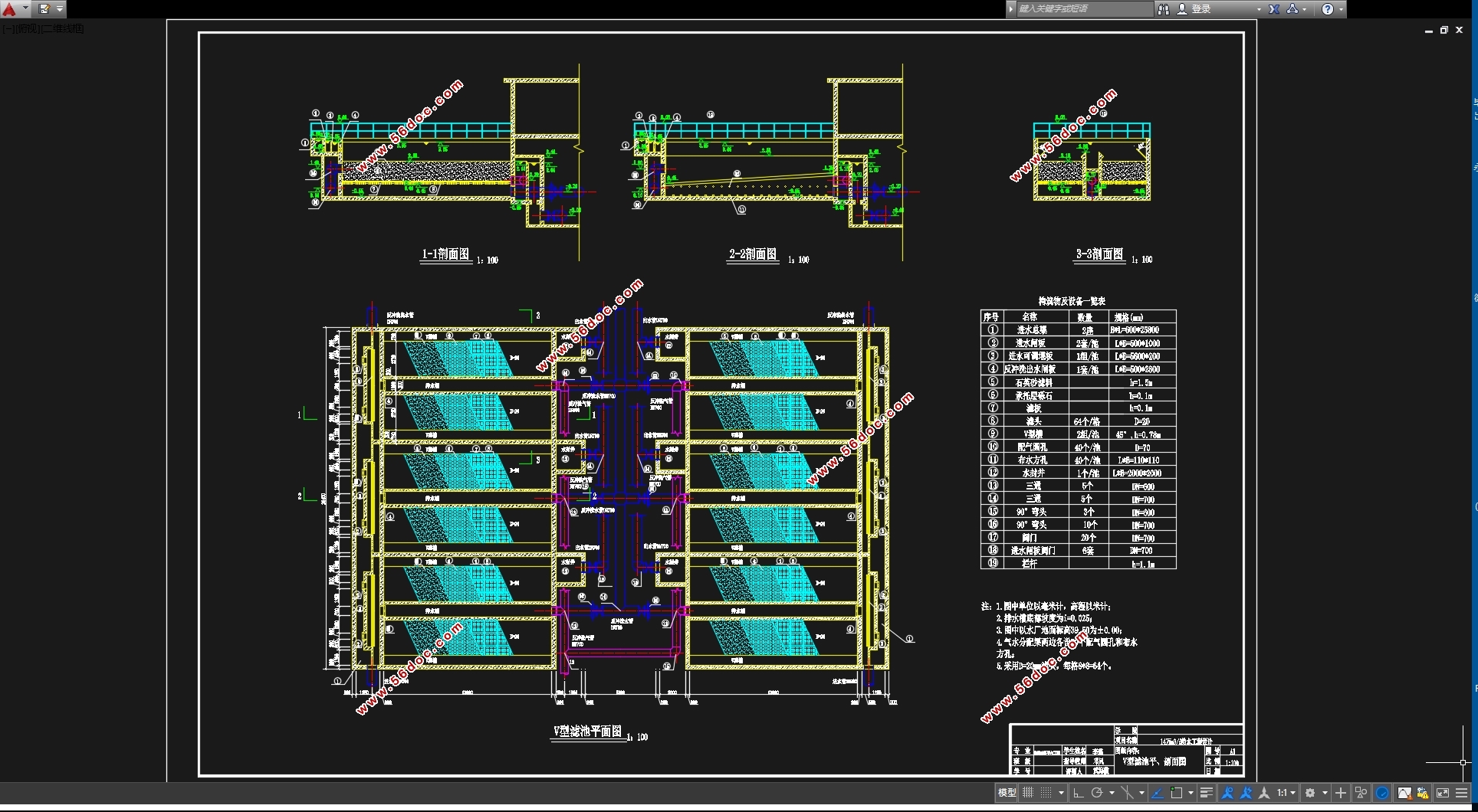
本课题设计内容为14万m3/d 规模的微污染水源给水工程设计,包括取水工程、净水工程、泵站、排泥水处理等。采用合建式岸边取水构筑物,取水泵房L×B×H=25.0m×10.0m×7.5m,选用三台S600-32 型号水泵,两台并联,一台备用,起重设备选用LDT4-S 电动单梁起重机。净水工艺采用常规(混凝沉淀、过滤及消毒)+臭氧生物活性炭深度处理工艺,混凝剂为聚合氯化铝,投加量为30mg/L,采用DN1000 管式静态混合器进行混合。絮凝池为2座折板絮凝池,每座絮凝池L×B×H=12.75 m×12.0 m×5.0m。沉淀池选用2座平流沉淀池,每座沉淀池L×B×H=144 m×12.0m×4.1m。6座V型石英砂滤池,双排布置,采用气水反冲,每座滤池L×B×H=13.0 m×7.0m×4.5m。
深度处理工艺选用臭氧—生物活性炭工艺,采用两次臭氧氧化,前臭氧设在絮凝之前,后臭氧与生物活性碳为联用。设两座前臭氧接触氧化池,每座尺寸为L×B×H=10m×4.0m×4.3m;后臭氧接触氧化池设两座,每座尺寸为L×B×H=10.0 m×4.0×4.3m。活性炭滤池采用生物活性炭技术,能有效去除水中有机物和嗅味等,周期可以延长到2~3年,因此不用再生。本设计中选用6座V型生物活性炭滤池,每座生物活性炭滤池的尺寸为L×B×H=15.0m×7.0m×5.2m。
消毒采用液氯为消毒剂,加氯量为1.0mg/L,加氯机选用型号C117/146美德国ALLDOS真空加氯机,1用1备。
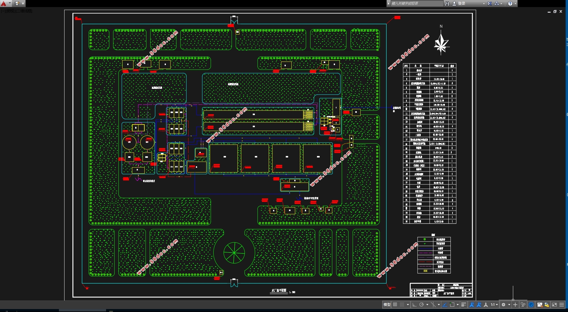
水厂排泥水主要来自絮凝沉淀的排泥水和滤池的反冲洗废水,水厂的排泥水量按日处理量的5%计算,即7350m3/d,排泥水均经过调节、浓缩后,上清液返回絮凝池进行回用处理,污泥经脱水最终制成泥饼外运。
关键词:微污染水源 常规工艺 深度处理 直饮水 排泥水
Abstract
With the rapid development of the economy and faster city changes, more and more surface water polluted by organic, Biochemical oxygen demand, ammonia, potassium permanganate index, more than "surface water environment quality standard" (GB3838-2002) class III, conventional treatment process can not achieve the "drinking water health standards" (GB5749-2006) requirements, pose a threat to the safety of drinking water, therefore the treatment of micro-polluted raw water is becoming the focus of attention.
This topic design content includes 140000 m3/d micro-polluted source water supply engineering design and sludge water treatment process design. Adopt Sub built shore water intake structures,( Water intake pump are three sets of S600-32 type water pump, two sets of parallel, one backup, hoisting equipment select LDT4-S electric single girder crane , Water intake pump house size is L×B×H=25.0×10.0×7.5m). Water purification process use the conventional process plus the polishing process of ozone activated carbon,( (conventional water purification process use PAC as coagulant, dosage is 30mg/L,use DN1000 tubular static mixer for mixing, Flocculation pool are Folded plate flocculation, each flocculation pool size is L × B × H=12.75 ×12.0 ×5.0m. Sedimentation tank is Advection sedimentation tank, each sedimentation tank size is L × B × H=144×12× 4.1m, Filtration process use6 seat V quartz sand filter, double row arrangement, adopt the gas and water recoil, each filter size is L × B × H=13.0× (3.5+3.5) × 4.5m.
Advanced treatment process select ozone biological activated carbon process,Ozone is divided into pre (before) the ozone oxidation and the main (rear) after ozone oxidation。Pre oxidation process, ozone is mainly to remove odor and taste, chroma , make water colloid particle destabilization, improve the effect of flocculation. The combined use of post oxidation process with activated carbon, mainly to kill bacteria and viruses. There are two pro ozone contact oxidation pool, two dosing and two contact chambers, each size is L×B×H=10.0×4.0×4.3m. There are three main ozone contact oxidation pool, three dosing and three contact chambers, each size is L×B×H=10.0×4.0×4.3m). Activated carbon filter use biological activated carbon technology, it can effectively remove organic matter and the smell of water, the cycle can also be extended to 2~3 years, so don't need to regeneration.(There are six V - shaped biological activated carbon filter in this design, each size is L×B×H=15.0m×7.0m×5.2m).
Disinfection use chlorine as the disinfectant, chlorine dosage is 1mg/L, chlorinator use C117/146 Germany ALLDOS vacuum chlorinator, 1 use 1 backup.
Sludge water is mainly from the sludge flocculation precipitation and backwashing water.Mud water is calculated by 5% of daily processing capacity, 7350m3/ days. Sludge, backwash water is adjusted, concentration, balance water flocculation precipitation, finally made of mud cake reuse. The treated sludge need reuse, sludge reached the sludge thickening tank after adjusted, the supernatant recycling, finally returns flocculation tank.
Keywords: micro polluted source water; conventional process; advanced treatment;drinking water; sludge water
1.1 设计资料
1.1.1 设计规模
本工程近期设计水量为14万m3/d,远期设计水量为近期水量的1.5倍,要求出厂水压达到46mH2O。
1.1.2 城市自然状况
(1) 地理位置:位于华东地区。
(2) 气温:年平均温度16℃,最高温度38.2℃,最低温度-6.5℃。
(3) 降雨量:年平均降雨量为983mm。
(4) 主导风向:夏季东南风,冬季东北风。
无自发性震源,强度在4级以下。
(5) 土壤冰冻深度:1m。
(6) 地下水水位:平均距地表3.8m。
1.1.3 水文及水质资料
1. 水文资料
水厂水源取自某一地表河流,河宽20米,其河岸平坦,枯水期主流离岸较远,河流流量Q为48~280m3/s,断面面积W为64~178m2,水流流速υ为0.8~1.5 m/s。
最高洪水位黄海标高38.5m,保证率95%的枯水期水位标高26.8 m,常水位标高30.2m,河床底标高20.2m。
水厂距水源地距离约1.25Km,水厂平均黄海标高为39.5m。
目录
摘 要 1
Abstract 2
目录 1
第一章 设计概况 1
1.1 设计资料 1
1.1.1 设计规模 1
1.1.2 城市自然状况 1
1.1.3 水文及水质资料 1
1.1.4 地质资料 2
1.1.5其它资料 2
1.2 设计成果 2
1.2.1 取水工程 2
1.2.2 净水工程 2
1.2.3 送水工程 3
1.2.4 工程投资估算及制水成本计算。 3
第二章 微污染水源水处理技术 4
2.1 原水分析 4
2.2 微污染水源预处理技术 4
2.3 强化常规工艺 6
2.4 微污染水源深度处理技术 6
第三章 取水构筑物设计 8
3.1 设计概述 8
3.2 方案比选 8
3.2.1取水头部选择 10
3.3 设计计算 10
3.3.1取水头部 10
3.3.2自流管 12
第四章 一级泵站 15
4.1 集水井设计计算 15
4.1.1格网计算 15
4.1.2集水井高程计算 16
4.1.3格网起吊设备 17
4.1.4排泥冲洗设备 18
4.2 取水泵站 18
4.2.1一泵流量和扬程 18
4.2.2水泵选型 19
4.2.3吸水管路及压水管路计算 20
4.2.4泵房布置 20
第五章 预处理工艺 22
5.1 设计概述 22
5.2 方案比选 22
5.3 设计计算 25
5.3.1气源系统 25
5.3.2臭氧发生系统 27
5.3.3臭氧-水的接触反应系统 28
5.3.4尾气处理系统 32
第六章 混凝 34
6.1 混凝剂 34
6.2 混合 41
6.2.1 混合设备的选择 41
6.2.2设计计算 43
6.3 絮凝池 44
6.3.1 絮凝池的选择 44
6.3.2 絮凝池设计计算 45
6.4 配水井 52
6.4.1设计参数 52
6.4.2设计计算 53
第七章 沉淀 54
7.1 沉淀池选型 54
7.2 设计计算 55
7.2.1设计水量 56
7.2.2平面尺寸计算 56
7.2.3进出水系统 57
第八章 过滤 63
8.1 滤池选型 63
8.2 设计计算 66
8.2.1滤池池体设计 67
8.2.2反冲洗管渠系统 70
8.2.3滤池管渠的布置 73
第九章 深度处理 83
9.1 设计概述 83
9.2 方案比选 83
9.3 设计计算 86
9.3.1生物活性炭滤池池体设计 86
9.3.2活性炭滤池反冲洗管渠系统 89
9.3.3活性炭滤池管渠布置 91
9.3.4反冲洗系统 93
第十章 消毒 99
10.1 消毒剂的选择 99
10.2 设计计算 102
第十一章 清水池 104
11.1平面尺寸计算 104
11.2管道系统 105
11.3清水池布置 107
第十二章 二级泵房 108
12.1吸水井 108
12.2二级泵房 109
12.2.1水泵选型 109
12.2.2吸水管路和压水管路 111
12.2.3泵房布置 111
第十三章 排泥水处理 113
13.1 排泥水处理工艺选择 113
13.2 干泥量的确定 115
13.3排泥水处理构筑物设计计算 116
13.3.1水量调节池 116
13.3.2浓缩池 117
13.3.3贮泥池 120
13.3.4污泥脱水 120
13.4控制系统 121
13.5排泥水处理构筑物高程计算 121
第十四章 水厂平面及高程布置 123
14.1水厂平面布置 123
14.1.1生产构筑物 123
14.1.2辅助构筑物 123
14.2水厂高程布置 124
第十五章 工程总概算 128
14.1水厂设施费用 128
14.2附属构筑物费用 128
14.3制水成本计算 129
参考文献 133
致谢 134
|