基于LabVIEW的脉搏检测系统设计(含硬件原理图,PCB图)
来源:56doc.com 资料编号:5D17327 资料等级:★★★★★ %E8%B5%84%E6%96%99%E7%BC%96%E5%8F%B7%EF%BC%9A5D17327
资料以网页介绍的为准,下载后不会有水印.资料仅供学习参考之用. 密 保 惠 帮助
资料介绍
基于LabVIEW的脉搏检测系统设计(含硬件原理图,PCB图)(论文10000字)
Design of pulse rate detection system based on LabVIEW
摘要
本课题以STC15单片机作为控制系统核心的心率测量仪的设计,以红外光电传感器作为检测人体心率脉搏的元件,采集到的心率脉搏信号再传送到单片机电路进行处理,得出的数据在LCD12864显示出来。当系统运行时,LCD12864显示是当前人体的脉搏心率跳动次数、脉搏波形,测量结束后显示的是最后一次测量脉搏心率跳动次数和脉搏波形。再通过单片机采集脉搏信号,利用功能强大的虚拟仪器LabVIEW设计出脉搏的采集与分析系统。在单片机上实现了采集脉搏传感器的模拟信号,然后通过串口将数据传输到上位机进行处理与分析,实现远程监控的功能。实验结果表明,系统工作正常,测量灵敏度高,实现了设计功能。
关键词:脉搏检测系统,STC15W408AS,红外光电传感器,串口,LabVIEW
Design of pulse rate detection system
Based on LabVIEW
Abstract
This topic for this STC15 single-chip microcomputer as a control system for the core of the heart rate meter design, with infrared receiving sensor as the detecting element of human pulse of heart rate, heart rate were collected pulse signal transmit to MCU circuit for processing, the data in LCD12864 display. When the system is running, the LCD12864 display is the current pulse rate of the pulse rate of the human body and the pulse waveform. After the measurement, the pulse rate of the pulse rate and pulse pulse are measured. By single-chip microcomputer to collect the pulse signal, the use of powerful LabVIEW virtual instrument design pulse acquisition and analysis system, on the single chip microcomputer to realize the collection of the analog signal of the pulse sensor and then through a serial port to transmit data to PC for processing and analysis, realizes the remote monitoring function. The experimental results show that the system works normally, the measurement sensitivity is high, and the design function is realized.
Keywords:Pulse detection system, STC15W408AS,infrared emission receiving sensor, serial port, LabVIEW
目录
1 引言 1
1.1 脉搏的研究背景与意义 1
1.2 选题意义 1
2 系统设计方案 1
2.1 实现的要求和功能 1
2.2 采集主控芯片方案 2
2.3 脉搏传感器的选择 2
2.4 上位机实现方案 4
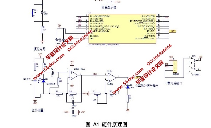
3 硬件电路设计 5
3.1 系统总框架 5
3.2 单片机模块 6
3.2.1主芯片STC15W408AS介绍 6
3.2.2 单片机最小系统模块 7
3.2.3电源电路 7
3.2.4复位电路 7
3.3 脉搏信号的采集 8
3.4 脉搏信号的处理 9
3.4.1低通滤波放大电路 9
3.4.2 电压比较器 9
3.4.3 运算放大器LM358 10
3.5 液晶显示模块 11
3.6 USB串口通信模块 12
4 系统软件设计 12
4.1测量计算原理 12
4.2 主程序流程介绍 13
4.3 显示程序流程 13
4.4 ADC 采用程序流程介绍 14
4.5 LabVIEW上位机程序设计 16
4.5.1 LaBVTEW串口通信配置 16
4.5.2 LabVIEW 脉值及波形显示 17
6 系统测试与结果分析 18
6.1下位机测试 18
8 误差分析与修正 20
总结 21
致谢 22
参考文献 23
附录 24
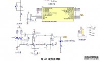
附录A硬件原理图 24
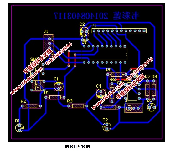
附录B PCB图 25
附录C 硬件外观图 26
附录D LabVIEW程序及前面板: 27
|