光纤温度测量系统的设计(附总体电路图,程序)
来源:56doc.com 资料编号:5D19112 资料等级:★★★★★ %E8%B5%84%E6%96%99%E7%BC%96%E5%8F%B7%EF%BC%9A5D19112
资料以网页介绍的为准,下载后不会有水印.资料仅供学习参考之用. 密 保 惠 帮助
资料介绍
光纤温度测量系统的设计(附总体电路图,程序)(课题说明书,开题报告,中期检查表,论文8500字)
摘 要 光纤技术在近几年得到了广泛的研究,在测量领域的地位逐年提高,而本文所讲的光纤温度测量系统就运用到了这一技术,其中是以光纤温度传感器TS3为基础来实现的,可以实现多点测温,还有报警功能。光纤温度测量系统的内部构成成分主要由以下几个方面组成:光纤温度传感电路、A/D转发电路,紧急停止电路等等。本文对TS3的操作流程、工作原理以及温度测量系统的运作机制进行了一个简单的介绍,并进行了软件仿真。仿真结果表明:基于光纤温度传感器TS3的温度测量系统具有良好的多点测温性能。
关键词 光纤温度传感器TS3: 多点测温: 温度测量
Design of Optical Fiber Temperature Measurement System
Abstract Fiber optic technology has been widely studied in recent years, and its position in the field of measurement has increased year by year. The fiber optic temperature measurement system described in this paper applies this technology, which is based on the fiber optic temperature sensor TS3. It can realize multi-point temperature measurement and alarm function. The internal components of the optical fiber temperature measurement system are mainly composed of the following aspects: optical fiber temperature sensor circuit, A/D forwarding circuit, emergency stop circuit and so on. In this paper, the operation process, working principle and operation mechanism of the temperature measurement system of TS3 are briefly introduced, and the software simulation is carried out. The simulation results show that the temperature measurement system based on optical fiber temperature sensor TS3 has good multi-point temperature measurement performance.
Keywords Optical Fiber Temperature Sensor TS3; Multi-point Temperature Measurement; Temperature Measurement
3.1方案设计
本文是基于传感型的光纤温度传感器能对自身的物理输出信号有着很高的自身可控性,设计出来一套以光纤温度传感器TS3和STC89C52单片机为核心的测量温度的系统。
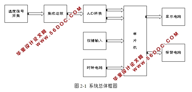
温度信号采集模块:当由于外界的环境等原因导致系统温度发生的时候,系统内部由二氧化硅等成分组成的石英光纤敏感头就会感知到,并接收这一信息,使得光纤的温度发生变化,最后由光电转换器接收光波信息,并将光信号转化为电信号[3]。
集成运放:由于采集到的温度信号比较微弱,需对其进行放大。
A/D转换模块:温度信号最终要送至单片机进行处理,要把模拟信号转换为数字信号。
按键输入模块:规定两个按键,这两个按键的作用分别是设置不同的温度区间一个可以调节它的最高温度范围,一个调节它的最低温度范围。调高和调低温度。
报警电路模块:当温度超过按键模块所设置的温度时,就会发出警告,再次重新调节温度。
显示电路模块;最后所测量的温度信号,转换到显示屏上,可以得到温度值。
当石英光敏传感触头由于外界温度而发生变化时,就会使得TS3开始对温度信号进行采集。然后将采集到的信号传输到STC89C52单片机,并通过一系列的转化输出数字信号,以此显示当前的温度值。
目 录
摘要及关键词.................................................................................................................................1
1 引言.............................................................................................................................................1
2 发展现状.....................................................................................................................................2
3 总体设计方案.............................................................................................................................2
3.1设计方案...............................................................................................................................2
3.2光纤传感器TS3....................................................................................................................3
4 硬件电路设计.............................................................................................................................6
4.1放大电路................................................................................................................................6
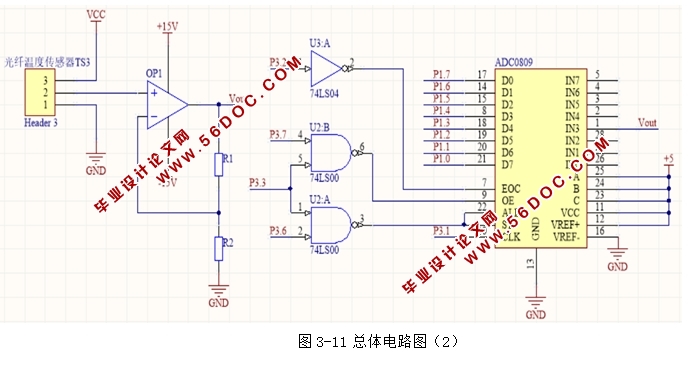
4.2A/D转换电路........................................................................................................................8
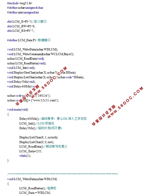
4.3 LCD显示电路.....................................................................................................................11
4.4报警电路..............................................................................................................................11
4.5按键电路..............................................................................................................................13
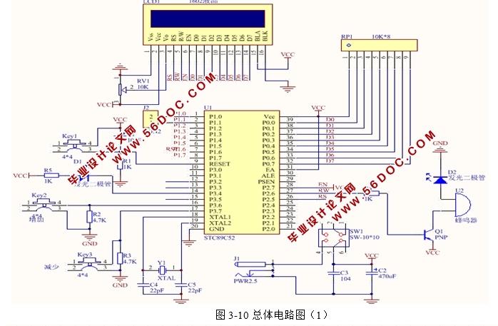
4.6系统硬件电路图..................................................................................................................13
5 软件系统设计...........................................................................................................................14
5.1主程序流程图......................................................................................................................15
5.2信号采集与处理流程图......................................................................................................15
5.3A/D转换流程图..................................................................................................................15
6 调试与仿真...............................................................................................................................15
7 结论...........................................................................................................................................15
参考文献.......................................................................................................................................16
致谢...............................................................................................................................................18
附录...............................................................................................................................................19
|
