移动电源电路设计
来源:56doc.com 资料编号:5D26716 资料等级:★★★★★ %E8%B5%84%E6%96%99%E7%BC%96%E5%8F%B7%EF%BC%9A5D26716
资料以网页介绍的为准,下载后不会有水印.资料仅供学习参考之用. 密 保 惠 帮助
资料介绍
移动电源电路设计(论文12700字)
摘要:
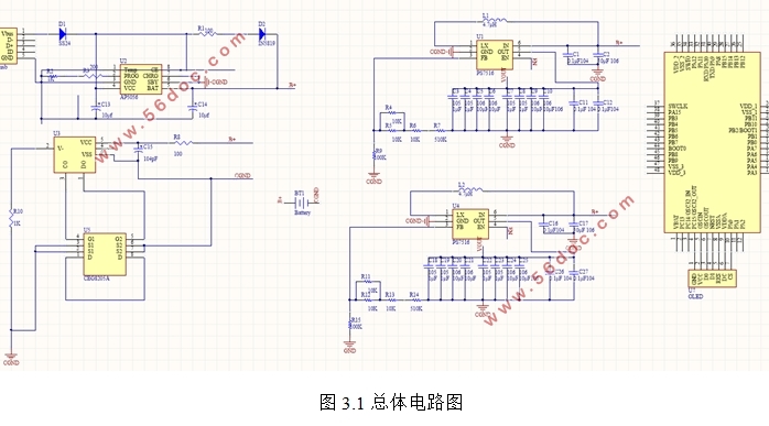
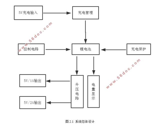
毕业设计旨在通过大学本科四年内所学的知识,设计出便携式移动电源的主电路图,主要是为了解决如今电子设备随时随地充电的要求。本次设计主要包括充电管理电路、充电保护电路、升压电路、控制电路。本次设计主要是利用AP5056相关的特性以及必要的外围电路对锂电池进行充电管理,采用的是恒流、恒压充电。保护电路主要是由DW01和CEG8205A来对锂电池进行过冲、过放、短路的保护。升压电路是利用PS7516和FP6716来对锂电池的电压能够升到5V/1A和5V/2A。控制电路利用STM32F103C8T6芯片来显示电量百分比、控制升压电路、进入待机模式以及唤醒措施设计。经过测试,硬件电路的功能总体上都能实现,软件工作也正常,能够基本上实现移动电源的基本功能。本次毕业设计精度误差在5%以内,达到毕业设计的基本要求。
关键词:移动电源单片机电路可携带
Circuit design of power bank
Abstract:The graduation design aims to design the main circuit diagram of portable mobile power supply through the knowledge of four years' undergraduate course, which is mainly to solve the current charging requirements of electronic devices anytime and anywhere. This design mainly includes charge management circuit, charging protection circuit, boost circuit and control circuit. The design is mainly based on AP5056 related characteristics and necessary peripheral circuits to charge and manage lithium batteries, which uses constant current and constant voltage charging. The protection circuit is mainly protected by overshoot, over discharge and short circuit of lithium battery by DW01 and CEG8205A. The boost circuit uses PS7516 and FP6716 to increase the voltage of lithium battery to 5V/1A and 5V/A. The control circuit uses STM32F103C8T6 chip to display power percentage, control boost circuit, enter standby mode and wake up measure design. After testing, the function of the hardware circuit can be realized in general, and the software work is normal. It can basically realize the basic function of the mobile power supply.The accuracy of the graduation design is within 5%, which meets the basic requirements of graduation design.
Keywords:power bank;Single Chip Microcomputer;circuit;portable


目录
1. 绪论 1
1.1研究目的和意义 1
1.2前言 1
1.3研究现状 1
1.4研究内容及论文结构安排 2
1.4.1电路设计 2
1.4.2软件设计 3
1.4.3论文结构安排 3
1.5本章小结 3
2.系统总体设计 4
2.1锂电池基本介绍 4
2.2系统的总体设计 4
2.3本章小结 5
3. 硬件电路设计 5
3.1总体电路设计 5
3.2充电管理电路 6
3.3充电保护电路 7
3.4升压电路 8
3.4.1 5V/1A输出 9
3.4.2 5V/2A输出 10
3.5控制电路 11
3.5.1主控制芯片 11
3.5.2 电量显示 12
3.5.3锂电池剩余容量百分比检测 12
3.5.4低功耗设计 13
3.5.5唤醒设计 14
3.6本章小结 15
4.软件设计 16
4.1 ADC采集 16
4.2 OLED电量显示 16
4.3 进入待机模式与唤醒设计 17
4.4本章小结 18
5. 测试 19
5.1硬件测试 19
5.1.1充电管理、保护电路 19
5.1.2 5V/1A升压电路 19
5.1.3 5V/2A升压电路 20
5.2软件测试 21
5.2.1OLED显示 21
5.2.2ADC采集 21
5.2.3电量百分比显示 21
5.2.4进入低功耗模式 22
5.2.5唤醒设计 22
5.3总体测试 22
6.总结与展望 23
6.1总结 23
6.2 展望 23
参考文献 24
致谢 25
|


