基于温度传感器的婴儿蹬被报警系统设计
来源:56doc.com 资料编号:5D21716 资料等级:★★★★★ %E8%B5%84%E6%96%99%E7%BC%96%E5%8F%B7%EF%BC%9A5D21716
资料以网页介绍的为准,下载后不会有水印.资料仅供学习参考之用. 密 保 惠 帮助
资料介绍
基于温度传感器的婴儿蹬被报警系统设计(任务书,论文13000字)
摘 要
本次设计的是婴儿蹬被报警系统。主要包括单片机最小系统、温度传感器、报警系统,按键模块以及显示模块五部分,先通过对硬件电路的五个部分进行研究设计,仿真采用protel99se,软件代码编程使用C语言,使各个模块之间能够实现各自的功能。温度传感器检测到温度的变化并且发送信号至单片机,单片机再通过判断驱动报警器报警。
论文首先介绍了婴儿蹬被报警系统的背景,然后在确定设计的思路和方案后确定了硬件部分的设计仿真,接着根据硬件部分的设计完成软件代码的编写,最后将软件与硬件结合后进行硬件调试。
关键词:温度 报警 单片机 温度传感器
The Baby kicking Alarm System Based on Temperature Sensor and MSP430
Abstract
This thesis studies the baby kicking alarm system. It can be divided into five parts: the MCU minimum system, temperature sensor, alarm system, key module and display module. At first, this paper introduces the design of the hardware circuit of the five parts. The circuit is simulated by protell99. The code program is written by C. So every module can realize the function of themselves.DS18B20 detects the temperature and send signals to SCM.SCM must judge if the alarm alarming.
The thesis introduces the background of the baby kicking alarm system. The design and simulation of hardware is designed after determining the idea. The code is written according to the design of hardware. At last, the software and hardware are combined for debugging.
Key Words: temperature; alarming; micro-controller; temperature sensor
目 录
第一章 绪 论 1
1.1 课题的背景 1
1.2设计的内容 1
1.3温度传感器的现状 2
第二章 系统整体方案 4
2.1系统整体框图 4
2.2方案论证和设计 4
第三章 系统硬件设计 6
3.1单片机最小系统 6
3.1.1 单片机的选择 6
3.1.2 单片机MSP430 的最小系统模块设计 7
3.2 温度测量部分模块 9
3.2.1 选择温度传感器DS18B20的原因 9
3.2.2 DS18B20的工作原理 10
3.2.3 DS18B20模块连接设计 12
3.3 键盘设置模块 13
3.3.1键盘的分类介绍 13
3.3.2 按键的选择和设计 14
3.4 报警电路模块 14
3.5 温度显示部分模块 15
3.5.1 温度显示元件的选择 15
3.5.2 NOKIA5110液晶显示介绍 16
3.5.3 液晶显示部分的连接和设计 18
第四章 系统软件设计 19
4.1 主程序的设计流程 19
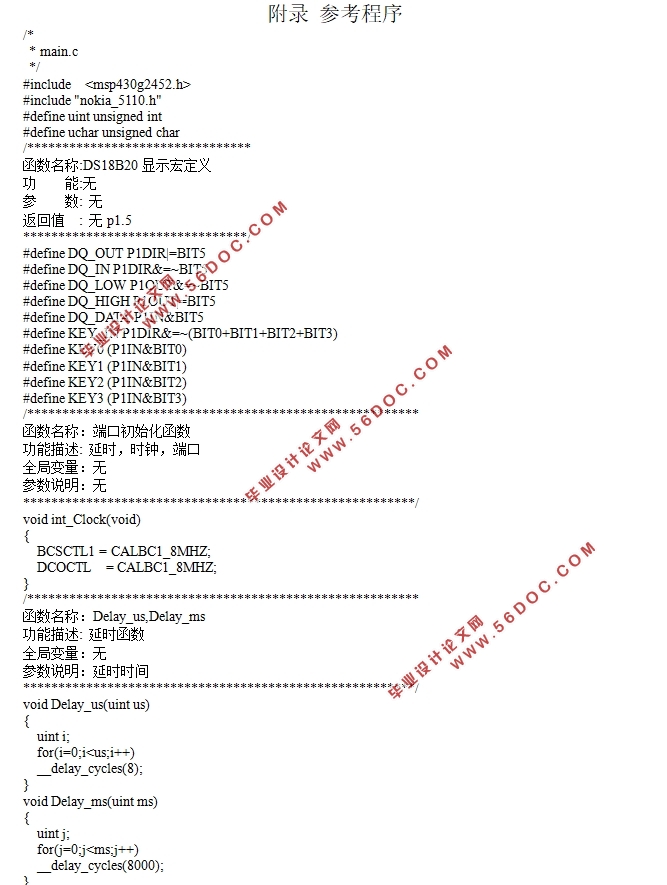
4.2 DS18B20的程序设计 20
4.2.1 DS18B20的分辨率设置 20
4.2.2 DS18B20的操作指令 21
4.2.3 子程序设计 21
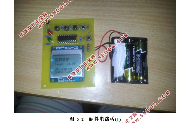
第五章 电路图与硬件结果 26
5.1 电路原理图 26
5.2 硬件调试 27
第六章 总结与展望 29
6.1 总结 29
6.2 展望 29
参考文献 31
附录 参考程序 32
致谢 45
|