基于51单片机的可调电压源设计
来源:56doc.com 资料编号:5D27953 资料等级:★★★★★ %E8%B5%84%E6%96%99%E7%BC%96%E5%8F%B7%EF%BC%9A5D27953
资料以网页介绍的为准,下载后不会有水印.资料仅供学习参考之用. 密 保 惠 帮助
资料介绍
基于51单片机的可调电压源设计(开题报告,外文翻译,论文12500字)
摘要
在当代科技与经济高速发展的过程中,电源起到关键性的作用。电源技术尤其是数控电源技术是一门实践性很强的工程技术,服务于各行各业。本设计基于51单片机设计制作的可调输出电压源作为调整输出电压的主控器件,通过调整滑动变阻器来改变输出电压。同时利用AD0832来实现A/D转换和向数码管提供显示信息。本系统主要有整流滤波模块、输出电压控制模块、AD转换模块、单片机、测温模块、数码管显示模块所组成,从而构成一个完整的数显可调稳压电源。该作品具有功耗低,输出电压稳定等优点。
关键字:输出电压;单片机;数码管;DS18B20
Design of adjustable voltage source based on 51 MCU
Abstract
In the process of the rapid development of science and technology and economy,power supply plays a key role.Power supply technology, especially numerical control power supply technology is a practical engineering technology,service to all walks of life.This design uses 51 as the main control device of the output voltage,the output voltage is changed by adjusting the sliding rheostat. At the same time, the use of A/D to achieve conversion and display information to the digital tube.The system mainly has the rectification filter module、output voltage control module、AD conversion moduleAD0832、MCU、Temperature measurement module、Digital tube display module.Thus constituting a complete digital adjustable power supply.The work has the advantages of low power consumption, stable output voltage, etc.
Key Words: Output voltage; MCU; Digital tube;DS18B20
目 录
摘要 I
Abstract II
第一章 绪论 1
1.1 可调节输出电压源的研究背景和意义 1
1.2 国内外发展现状 1
1.3 论文框架及结构安排 2
第二章 设计要求和方案论证 3
2.1 设计要求 3
2.2 系统设计方案及其论证 3
2.2.1 主控芯片的选择 3
2.2.2 显示模块的方案选择 4
2.2.3 开关稳压电源控制器的选择 4
2.2.4 温度传感器选择 4
2.2.5 电路设计的最终方案 5
第三章 硬件电路的设计 7
3.1 STC89C51单片机主控系统设计 7
3.1.1 STC89C51简介 7
3.1.2 STC89C51主要功能和性能参数 7
3.1.3 STC89C51单片机引脚说明 7
3.1.4 时钟电路 9
3.1.5 复位电路 9
3.2 连续可调开关稳压电源电源电路模块 10
3.2.1 整流滤波电路 10
3.2.2 输出电压控制电路的设计 10
3.3 AD转换与显示电路的设计 12
3.4 温控电路 14
3.4.1 引脚功能介绍 15
3.4.2 DS18B20的工作原理 16
3.5 继电器驱动电路 17
第四章 系统的软件设计 19
4.1 软件开发环境 19
4.2 软件体系总结构 19
4.3 微控制器模块程序设计 20
4.4 温度监测模块程序设计 20
4.5 数码管显示程序设计 23
第五章 系统的调试与测试结果 25
5.1 系统的软件调试 25
5.2 系统的硬件调试 26
5.3 测试结果 28
5.4 设计遇到的问题及其解决方法 28
第六章 结语 30
参考文献 31
致谢 32
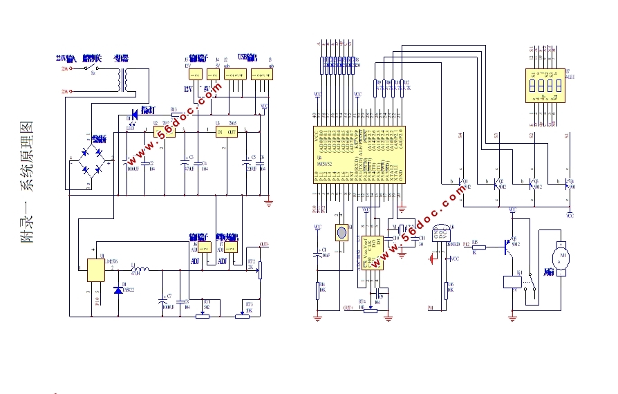
附录一 系统原理图 33
附录二 系统实物图 34
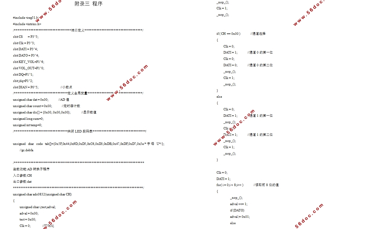
附录三 程序 35
|