汽车后翼子板成型工艺与模具设计(附CAD图,UG三维图)
来源:56doc.com 资料编号:5D13351 资料等级:★★★★★ %E8%B5%84%E6%96%99%E7%BC%96%E5%8F%B7%EF%BC%9A5D13351
资料以网页介绍的为准,下载后不会有水印.资料仅供学习参考之用. 密 保 惠 帮助
资料介绍
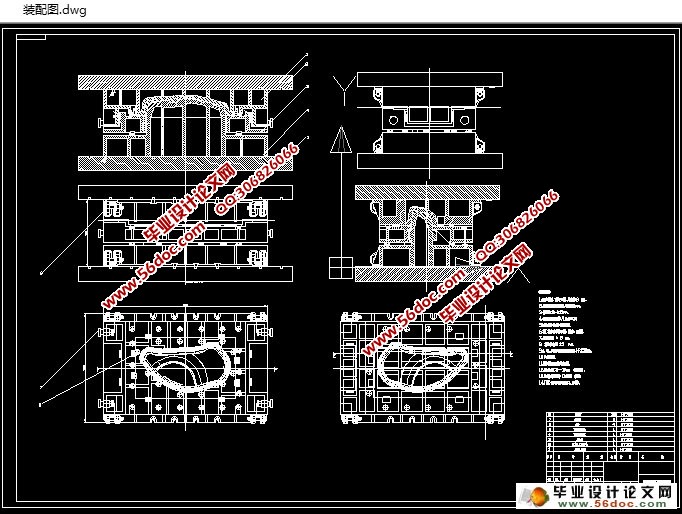
汽车后翼子板成型工艺与模具设计(附CAD图,UG三维图)(任务书,开题报告,外文翻译,论文说明书10000字,CAD图纸4张,UG图纸5张)
摘要
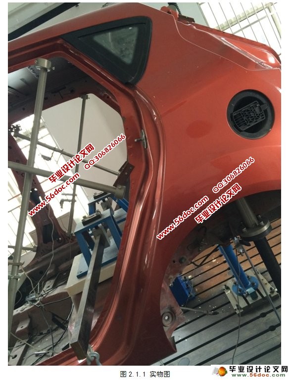
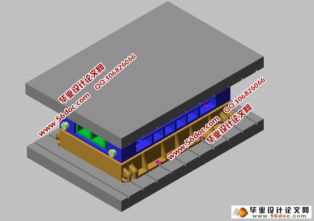
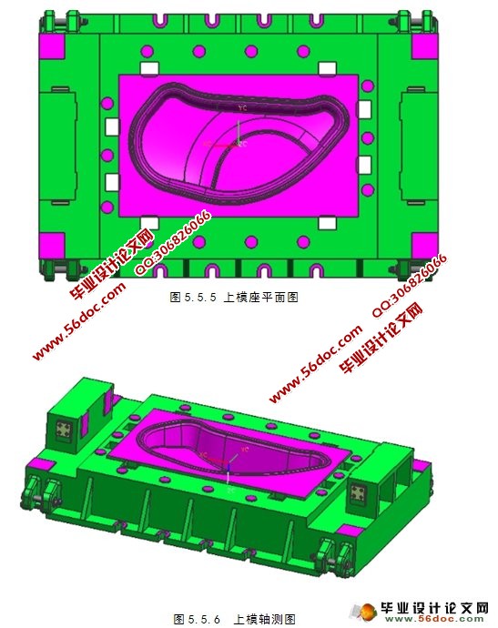
本篇论文以型号为马自达3的汽车的左后翼子板为实例,具体地分析其成型工艺特点,得出了汽车覆盖件冲压件成型工艺的共性。论文中介绍了汽车覆盖件成型的特点和外覆盖件的成型模具设计的基本原则。此次,直接用GEOMAGIC扫描实物图,并用三维软件画出三维模型,并完成了覆盖件的模具设计,更充分地反应了模具零件之间的装配关系,大大地减少了现实的模具设计所花费的时间和随之而产生的问题。
此次毕业设计的目的是加深对所学知识的掌握和对所学知识的综合利用,尤其是在完成设计的过程更多考虑到实际生产中的方面。对于设计时遇到的难点和疑点,运用可以查阅到的资料,很好地解决了相关的问题,这使自身在专业方面解决问题的能力得到了很大的提高。
关键字:后翼子板 拉延模具 冲压工艺 模具设计
Moulding process and die design of rear fender of car
Abstract
This paper with the Mazda 3 left rear fender as an example, in particular analysis of the forming characteristics and figure out the car covering parts stamping parts forming the common.Which shows the forming characteristics of automobile covering parts and cover drawing die design of the basic principles, the commonly used method of stamping direction, addendum surface design. The direct with Geomagic scanning physical map and 3D software is aim to figure out the maps and 3D models, and complete coverage of the mold design, more realistically reflect the assembly relation between parts of a mold, reduce some problems and time which the actual mould design brings.
The graduation design is to improve the skills to use knowledge, the comprehensive utilization of knowledge. Especially in the design process we take into account the actual production. The design difficulties and doubts can be solved through access to relevant information and good ability of self is trained to deal with the problem.
Key words:rear fender ;Drawing die;Stamping process;mould design
目 录
摘要 III
Abstract IV
1 绪论 1
1.1 引言 1
1.2 课题选题背景及研究内容 1
1.3 汽车覆盖件 2
1.4 覆盖件模具的种类 3
2 工件尺寸的测量 4
2.1 三维扫描和数据处理 4
3 汽车后翼子板的成型工艺方案的确定 7
3.1 工件材料的选择 7
3.2 工艺流程的确定 7
3.3 工艺补充部分 7
4 汽车后翼子板成型工艺设计 9
4.1 落料工艺设计 9
4.2 拉深工艺设计 9
4.3 修边工艺设计 10
4.4 翻边工艺设计 11
5 汽车后翼子板拉延模具设计 13
5.1 拉延模的选用 13
5.2 拉延模具尺寸的计算 13
5.3 汽车覆盖件冲压力的计算 14
5.4 拉延模凸模的设计 15
5.5 拉延模凹模的设计 16
5.6 压边圈的设计 19
5.7 导板的设计 21
5.8 压力机的选择 21
5.9 其他零件的设计 21
结论 23
参考文献 24
致 谢 25
|

