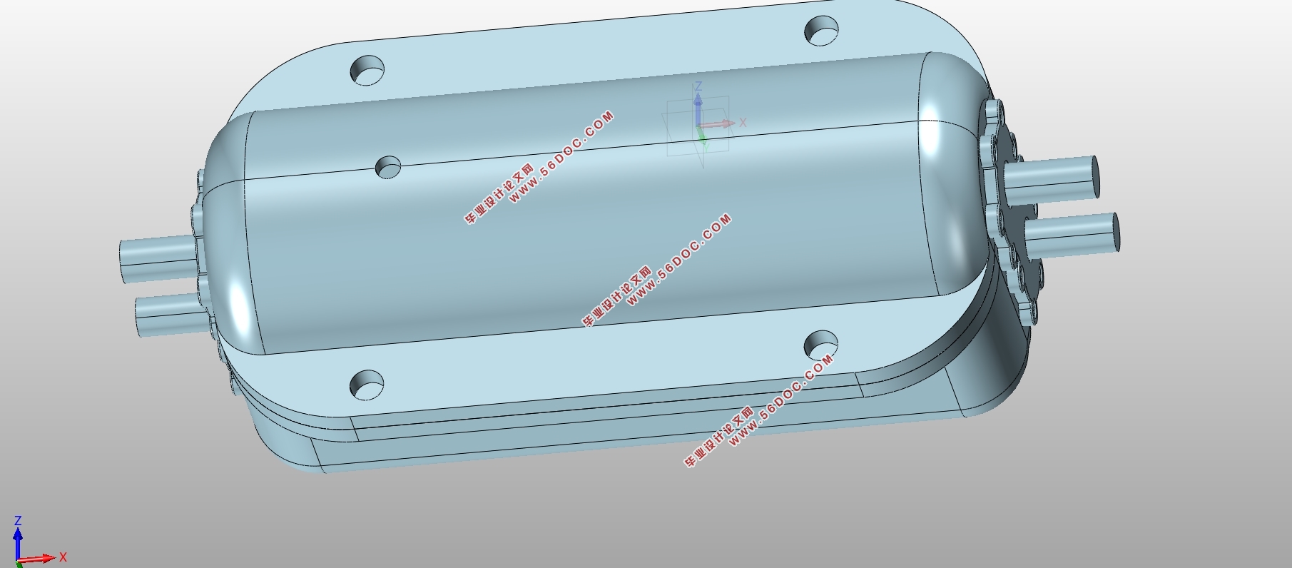
哈弗H6型SUV变速器设计(含CAD零件图装配图,STP三维图)(任务书,开题报告,外文翻译,文献摘要,论文说明书12000字,CAD图13张,STP三维图)
摘 要
该设计专为哈弗H6乘用车而设计,考虑乘用车舒适性,操作简便性,动力性能和燃油经济性。在这里的研究中,采用六速机械两轴动力传递方案。作为扭矩传导和车速更替的重要装置,对变速器的设计的门槛越来越高。目前,四档,特别是五档变速器的应用率正在增加,也有很多车采用六档变速器装车。由于传动线路布置限制,前置后驱车传动结构使用两轴式。本次论文使用锁环同步换档设备档位变换更快速、精准。其中利用惯性原理设计的同步器装车最为普遍。依据设计方式的不同 ,其种类分为锁销式,滑块式,锁环式,多件式和多锥式。本次设计使用锁环同步器。设计过程包括各零件的参数设计,转动路径的布置,变速器各部件类型选择以及其强度验证。在结构设计中,利用SolidWorks软件执行三维建模和结构分析。
关键词:哈弗H6;两轴六档机械变速器;设计与校核
Abstract
This design aimed at harvard H6 passenger car, the comprehensive consideration of passenger car on ride comfort, ease operation, power performance and fuel economy requirements, in sixth gear mechanical transmission design. As an important device for transmitting power and changing speed, the transmission speed of transmission is higher and higher in foreign countries. Now especially for 4 5 gear transmission has a growing trend of application of at the same time, 6 block transmission of the loading rate is rising with two shaft type transmission structure, adopts the lock ring synchronizer shifting mechanism at the same time, makes the shifting more timely, more accurate, more stable. There are many kinds of synchronizers, which are generally divided into normal pressure, inertia and inertia force. Among them, inertial synchronizer is the most widely used. According to the structural difference inertia type synchronizer is divided into the lock pin type, the sliding block type, the lock ring type, the multichip type and the multi-cone type several. The lock ring synchronizer is adopted in this design. The design process includes dynamic parameter analysis, transmission ratio distribution, transmission structure design and the check of each component strength. In the structure design, SolidWorks software is used to conduct 3d modeling and structural analysis, and finally the drawing of engineering drawings is completed according to the parameters determined.
Key words:Harvard H6;6 block transmission; design and check


目 录
第1章绪论 1
1.1 课题研究的背景 1
1.2 世界范围内变速器的发展情况 1
第2章变速器类型与主要参数的选择 3
2.1设计初始数据 3
2.2 哈弗H6变速器各级传动比的设计 3
2.2.1 主减速比的确定 3
2.2.2 确定一档传动比 4
2.2.3 设计其余各档传动比 5
2.3 初步确定输入轴与输出轴间距大小 6
2.4 确定齿轮的模数,压力角,螺旋角,齿宽,齿顶高系数等参数 7
2.4.1 确定齿轮的模数 7
2.4.2 确定齿轮的压力角 7
2.4.3 确定齿轮的螺旋角β 8
2.4.4 确定齿轮的齿宽b 8
2.4.5 确定齿轮的齿顶高系数 8
2.5 本章小结 8
第3章各档位齿轮的各参数准确计算及其强度校核 10
3.1 确定一档倒挡直齿轮齿数和其余档位斜齿轮齿数的准确值 10
3.2 齿轮材料的选择原则 17
3.3 输入输出轴的各档位轴段的扭矩设计 18
3.4 齿轮弯曲强度和接触应力的校核 18
3.4.1 弯曲强度的校核 18
3.4.2 轮齿接触应力σj 25
3.5 本章小结 26
第4章轴的设计与计算及轴承的选择与校核 27
4.1 轴的设计计算 27
4.1.1 两根轴加工工艺的区别 27
4.1.2 大概确定两根轴的直径 27
4.1.3 三根轴的强度计算 27
4.2 轴承的选择及校核 31
4.2.1 输入轴的轴承选取与研究 31
4.2.2 输出轴的轴承选择与校核 33
4.3 本章小结 34
第5章同步器设计 35
5.1 锁环式同步器结构及其工作原理 35
5.2 主要建模元件--同步环的参数确定 36
第6章结论 37
参考文献 39
致谢 40
|


