新能源车型(奇瑞eQ1)前制动器设计(英文版)(含CAD图,CATIA三维图)(任务书,开题报告,外文翻译,文献摘要,论文说明书英文版10000字,CAD图5张,CATIA三维图)
Front brake design for a new energy car (referring to CHERY eQ1)
Abstract
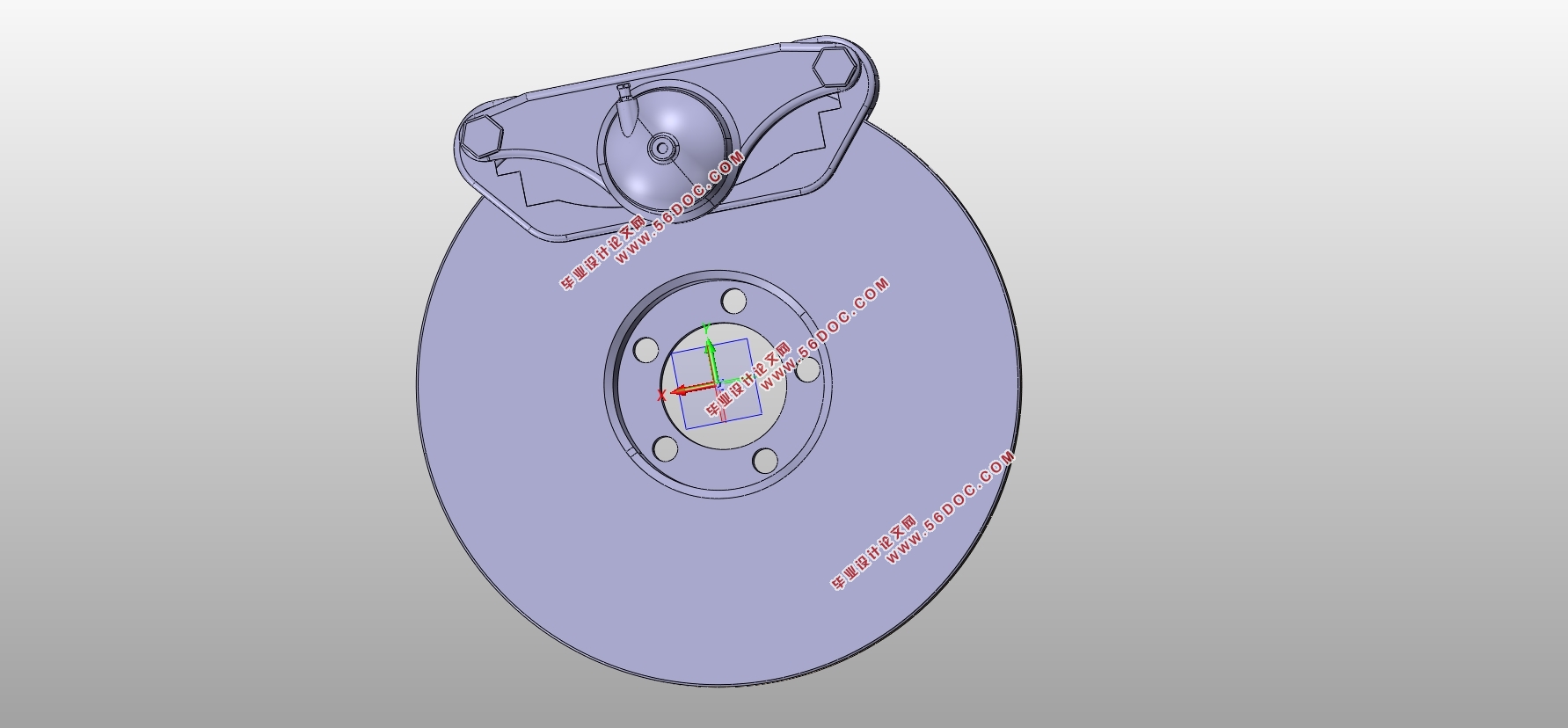
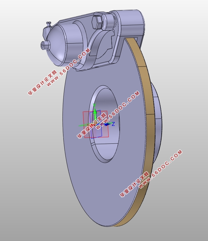
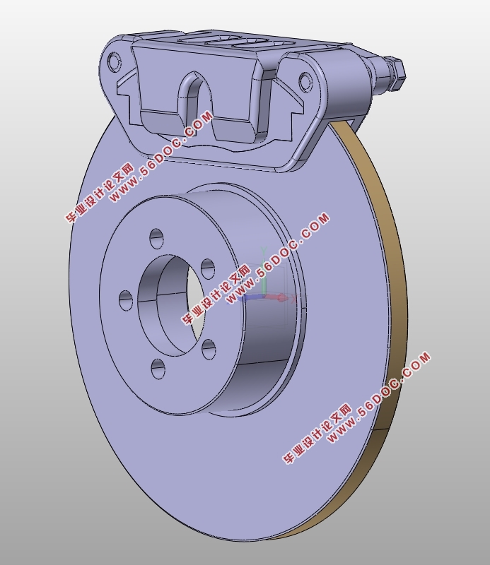
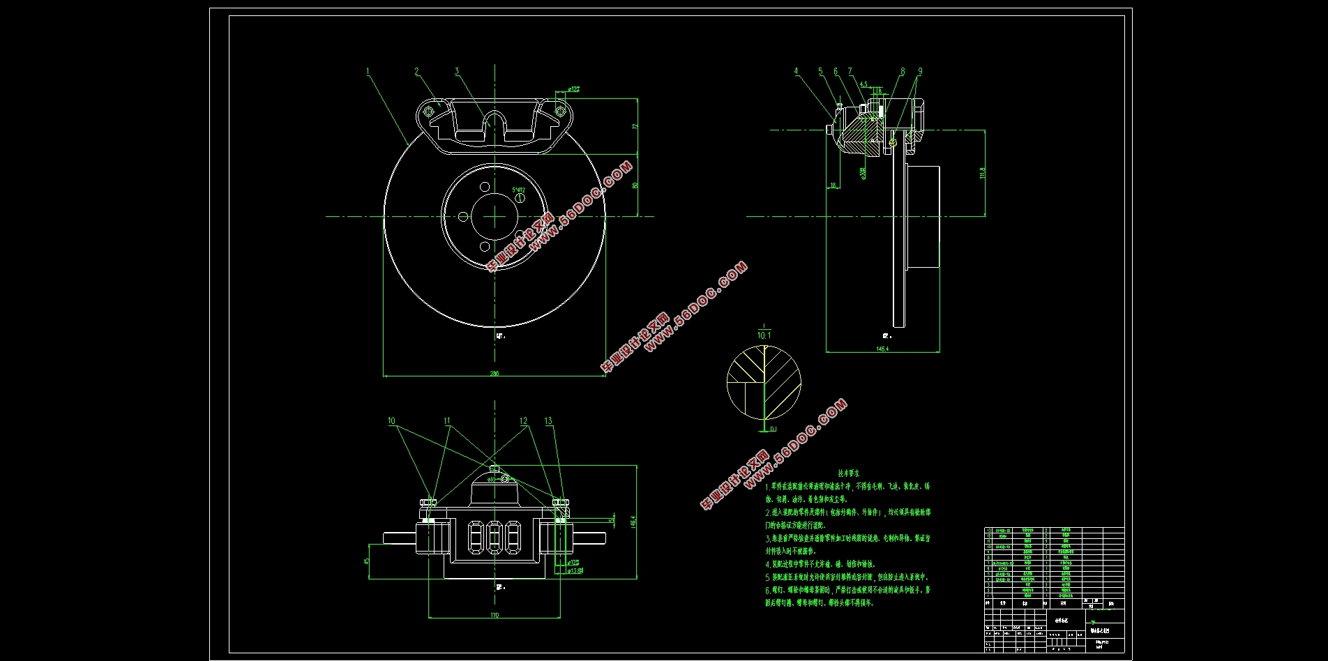
This paper introduces the classification of disc brakes and the advantages and disadvantages of various disc brakes, and it also selects the design schemes of the Chery eQ1’s front brake, then designs and calculates its basic parameters (such as the front and rear braking force distribution coefficient, the synchronous adhesion coefficient, the adhesion utilization, braking efficiency etc.) After that, these basic parameters are used to design and check the dimensions of the main brake components, such as brake discs and brake pads. The materials of these components are also selected according to the demands and requirements. In addition, the designed front brake of Chery eQ1 are modeled in 3D by using CATIA software, and the simulation analysis was carried out using the finite element software ANSYS. In that way is the performance of the front brake’s main component vividly analyzed, which can verify the reliability of the brake’s working.
Key Words:Disc brake; CATIA; 3D model; ANSYS; Finite element analysis
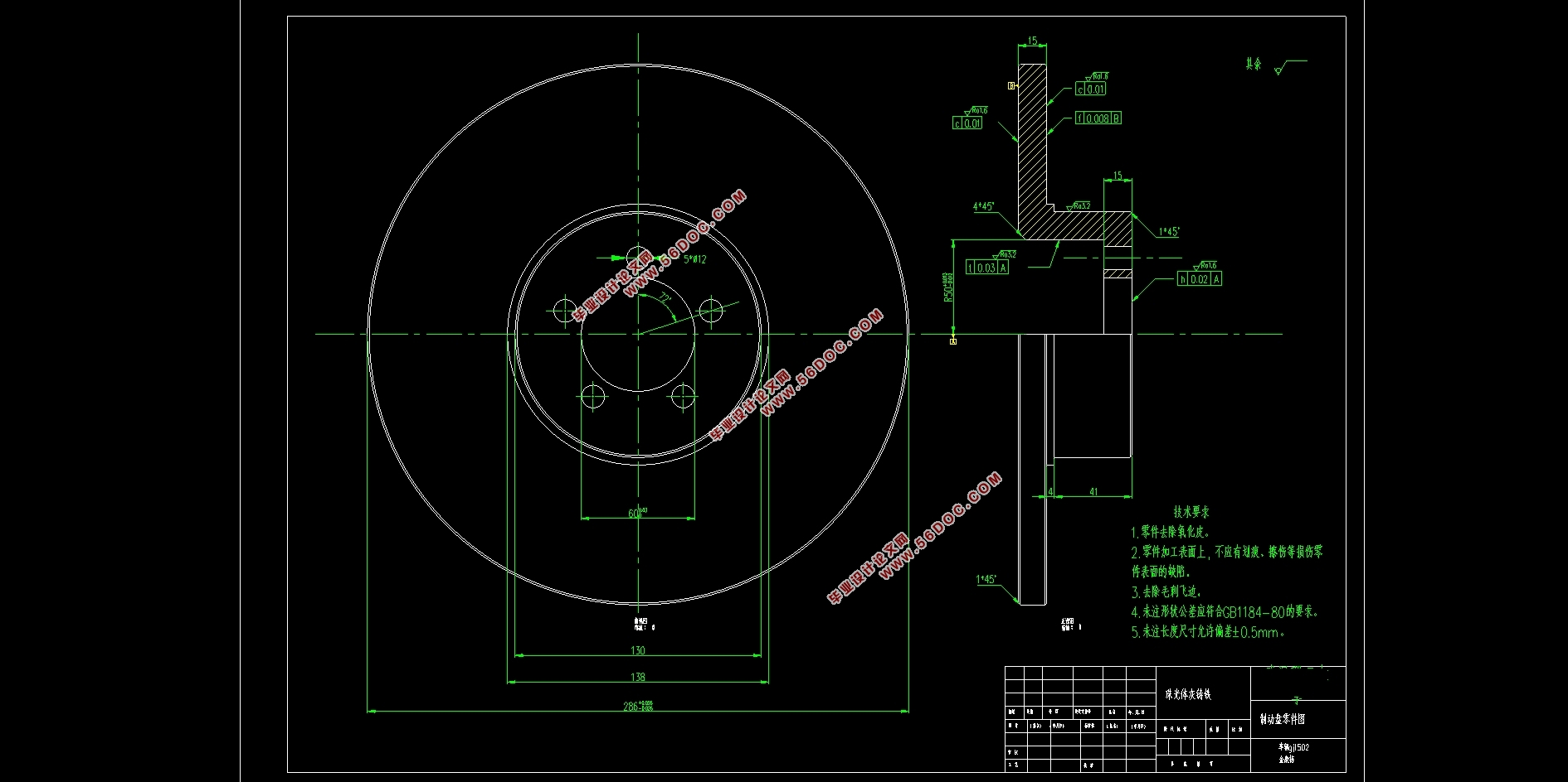

Contents
Chapter 1 Introduction 1
1.1 Function of brake 1
1.2 Different types of brake devices 1
1.3 The components of brake 1
1.4 New developments for brake 2
1.5 Requirements for brake 3
1.6 Tasks of the design 4
1.7 Design Schema 5
Chapter 2 Selection of brake’s structure 6
2.1 Basis for brake structure selection 6
2.2 Wheel brake’s type 6
2.3 Comparison between drum and disc type 6
2.4 Structure of disc brake and it’s selection 8
2.5 Structure decision for Chery eQ1’s front brake 11
Chapter 3 Design and selection of the brake’s main parameters 13
3.1 Basic parameters of Chery eQ1 13
3.1.1 Wheel rolling radius 14
3.1.2 Centroid height 14
3.2 Braking force and braking force distribution coefficient 14
3.3 Calculation of the synchronous adhesion coefficient 17
3.4 Maximum braking torque 19
3.5 Adhesion utilization coefficient and braking efficiency 22
3.5.1 Adhesion utilization 22
3.5.2 Braking efficiency , 24
3.6 Brake performance check 25
Chapter 4 Design, calculation and check of the brake’s main parts 26
4.1 Determination of brake disc’s main parameters 26
4.1.1 Brake disc diameter 26
4.1.2 Brake disc thickness 26
4.2 Determination of main parameters of friction pad 27
4.2.1 Inner and outer radius of the friction pad , 27
4.2.2 Friction pad friction coefficient 28
4.2.3 Friction pad effective radius 28
4.2.4 Calculation of area and wear characteristics of friction pads 29
4.2.5 Friction pad’s parameters check 31
4.3 Design and calculation of hydraulic brake drive mechanism 32
4.3.1 Brake wheel cylinder diameter and working volume 33
Chapter 5 Structure design of the brake’s main parts 35
5.1 Brake disc 35
5.1.1 Brake disc material and requirements 35
5.1.2 Brake disc classification and comparison 35
5.2 Brake caliper 36
5.3 Brake pads 37
5.4 Friction material 38
Chapter 6 3D modeling of the brake 40
6.1 Brake disc modeling 40
6.2 Brake pads modeling 41
6.3 Brake piston modeling 41
6.4 Brake caliper modeling 41
6.5 Overall assembly 43
Chapter 7 Modal analysis and parameter optimization of the brake disc 44
7.1 Finite element modal analysis of the brake disc 44
7.1.1 Introduction to modal analysis 44
7.1.2 Model pre-processing 45
7.1.3 Solve 47
7.1.4 Result of the modal analysis 49
7.2 Parameter optimization of the brake disc 50
7.2.1 Target parameter selection 50
7.2.2 Parameter modification of the brake disc 51
7.2.3 Modal analysis result of the modified model 52
7.2.4 Result of the parameter optimization 53
Conclusion 54
References 55
|


