НЮЗПГЕКѓаќМм(ЫЋКсБлаќМм)ЩшМЦ(КЌCADСуМўЭМзАХфЭМ)
РДдДЃК56doc.com зЪСЯБрКХЃК5D25273 зЪСЯЕШМЖЃКЁяЁяЁяЁяЁя %E8%B5%84%E6%96%99%E7%BC%96%E5%8F%B7%EF%BC%9A5D25273
зЪСЯвдЭјвГНщЩмЕФЮЊзМ,ЯТдиКѓВЛЛсгаЫЎгЁ.зЪСЯНіЙЉбЇЯАВЮПМжЎгУ. Ум БЃ Лн Аяжњ
зЪСЯНщЩм
НЮЗПГЕКѓаќМм(ЫЋКсБлаќМм)ЩшМЦ(КЌCADСуМўЭМзАХфЭМ)(ШЮЮёЪщ,ПЊЬтБЈИц,ТлЮФЫЕУїЪщ16000зж,CADЭМ5еХ)
еЊ вЊ
НЮЗПГЕЪЧвЛжжФПЧАЪаУцЩЯЛЙУЛгаЕФШЋаТГЕаЭЃЌНЮЗПГЕЦНГЃзїЮЊНЮГЕЪЙгУЃЌГіШЅТУааЪЧПЩвдБфаЮГЩЗПГЕЪЙгУЁЃвђДЫашвЊЩшМЦвЛжжМШФмБЃжЄНЮЗПГЕСМКУЪцЪЪадгжФмБЃжЄПЩППадЕФНЮЗПГЕКѓаќМмЁЃ
ИљОнЦћГЕЩшМЦвЊЧѓгыВНжшЃЌдйНсКЯНќФъРДЦћГЕаќМмСьгђЕФбаОПНјеЙЃЌБОТлЮФШЗЖЈСЫНЮЗПГЕКѓаќМмЕФНсЙЙаЮЪНКЭжївЊВЮЪ§ЃЌНшжњМЦЫуЛњИЈжњЩшМЦШэМўCATIAНјааНсЙЙЩшМЦЃЌВЂЭЈЙ§ANSYSШэМўНјааЧПЖШЗТецЗжЮіЃЌЭЈЙ§ADAMSШэМўНјаадЫЖЏЗТецНтОідЫЖЏИЩЩцЮЪЬтЁЃОпЬхЩшМЦЗжЮЊвдЯТЫФИіЙ§ГЬЁЃ
ЃЈ1ЃЉЗжЮіЙњФкЭтЦћГЕКѓаќМмНсЙЙаЭЪНЃЛШЗЖЈНЮЗПГЕКѓаќМмРраЭЁЃ
ЃЈ2ЃЉШЗЖЈНЮЗПГЕКѓаќМмЩшМЦЗНАИКЭММЪѕВЮЪ§ЁЃ
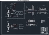
ЃЈ3ЃЉЩшМЦКѓаќМмжївЊСуВПМўВЂЭъГЩаќМмзАХфЁЃ
ЃЈ4ЃЉаќМмЧПЖШКЭдЫЖЏЗТецЗжЮіЁЃ
НсЙћБэУїЫљЩшМЦНЮЗПГЕКѓаќМмНсЙЙКЯРэЃЌЧПЖШЗћКЯвЊЧѓЁЃЫљЕУНсЙћеыЖдНЮЗПГЕКѓаќМмЩшМЦОпгаживЊЕФВЮПМвтвхЁЃ
ЙиМќДЪЃКНЮЗПГЕЃЛЫЋКсБлаќМмЃЛТна§ЕЏЛЩЃЛЗТец
Abstract
Saloon-Recreational Vehicle is a new concept car which has not existed in market. New Recreational Vehicle is used as saloon car in daily life, while it is used as recreational vehicle in period of travelling. Therefore, suspension need to be designed to meet the requirements of travelling comfort and reliability.
According to the requirements and steps of automotive design, coupled with recent advances of the research in the field of automobile suspended frame, This paper determines structure and main parameters of New Recreational Vehicle rear suspension. With the aid of computer aided design software CATIA structural design is accomplished, and strength analysis is accomplished by ANSYS. Beside, motion interference problem is solved by simulation software ADAMS. The concrete research process is divided into the following steps.
1) Analyzing domestic and foreign automobile suspension structure; determining its rear suspension type.
2) Determining rear suspension design scheme and technical parameters.
3) Designing the major parts of the rear suspension; completing the suspension assembly.
4) Suspension strength and motion simulation analysis.
Results show that the rear suspension structure is reasonable, the strength meets the requirement. The result has important guiding significance for suspension design.
Key WordsЃКNew Recreational Vehicle Double wishbone suspension Helical spring Simulation

ФП ТМ
Ек1еТ аї Тл 1
1.1 ТлЮФбаОПЕФФПЕФМАвтвх 1
1.2 ЙњФкЭтбаОПЯжзД 1
1.3 ЩшМЦЕФЛљБОФкШн 2
Ек2еТ ЙњФкЭтЦћГЕКѓаќМмНсЙЙаЭЪНЗжЮі 3
2.1 ЙњФкЭтКѓаќМмЛљБОНсЙЙаЮЪЦЗжЮі 3
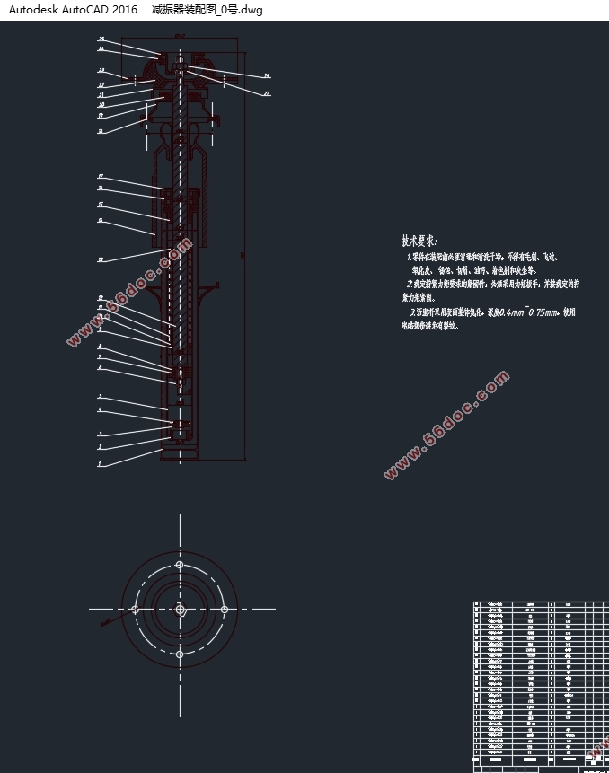
2.2 НЮЗПГЕКѓаќМмбЁаЭЗжЮі 4
2.3 БОеТаЁНс 5
Ек3еТ НЮЗПГЕКѓаќМмжївЊВПМўЬиад 6
3.1 КѓаќМмЕЏаддЊМўЬиадЗжЮі 6
3.2 КѓаќМмМѕеёЦїЬиадЗжЮі 6
3.3 БОеТаЁНс 7
Ек4еТ НЮЗПГЕКѓаќМмжївЊВЮЪ§ЕФШЗЖЈ 8
4.1 КѓаќМмОВФгЖШКЭЖЏФгЖШ 8
4.2 КѓаќМмВрЧуНЧИеЖШМАЦфдкЧАЁЂКѓГЕжсЩЯЕФЗжХф 10
4.3 БОеТаЁНс 10
Ек5еТ НЮЗПГЕКѓаќМмМАЦфВПМўЕФЩшМЦМЦЫу 11
5.1 НЮЗПГЕЫЋКсБлКѓаќМмЕМЯђЛњЙЙЩшМЦ 11
5.1.1 ЕМЯђЛњЙЙЩшМЦвЊЧѓ 11
5.1.2 ЕМЯђЛњЙЙЕФВМжУВЮЪ§ 11
5.1.3 аќМмКсБлЕФЖЈЮЛНЧ 12
5.1.4 знЯђЦНУцФкЩЯЁЂЯТКсБлЕФВМжУЗНАИШЗЖЈ 12
5.1.5 КсЯђЦНУцФкЩЯЁЂЯТКсБлЕФВМжУЗНАИШЗЖЈ 13
5.1.6 ЫЋКсБлаќМмЩЯЯТКсБлГЄЖШЕФШЗЖЈ 14
5.1.7 БОеТаЁНс 14
5.2 ЫЋКсБлКѓаќМмЕЏаддЊМўЩшМЦ 15
5.2.1 КѓаќМмТна§ЕЏЛЩЕФИеЖШЩшМЦ 15
5.2.2 ЕЏЛЩИеЖШаЃКЫ 17
5.2.3 БОеТаЁНс 18
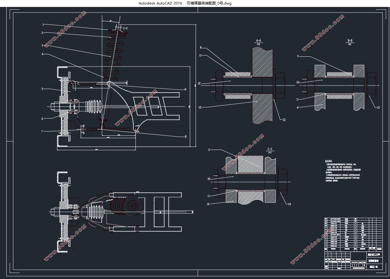
5.3 ЫЋКсБлКѓаќМмМѕеёЦїЩшМЦ 18
5.3.1 ЯрЖдзшФсЯЕЪ§ЕФШЗЖЈ 18
5.3.2 МѕеёЦїзшФсЯЕЪ§ЕФШЗЖЈ 19
5.3.3 МѕеёЦїзюДѓаЖКЩСІF0ЕФШЗЖЈ 20
5.3.4 ЭВЪНМѕеёЦїЙЄзїИзжБОЖЕФШЗЖЈ 21
5.3.5 БОеТаЁНс 22
Ек6еТ CATIAШ§ЮЌНЈФЃ 23
6.1 ЕЏаддЊМў 23
6.2 МѕеёЦї 24
6.3 ЕМЯђЛњЙЙ 24
Ек7еТ НЮЗПГЕКѓаќМмЗТецЗжЮі 26
7.1 КѓаќМмгІСІгІБфЗТецЗжЮі 26
7.2 КѓаќМмдЫЖЏЗТецЗжЮі 27
Ек8еТ змНсгыеЙЭћ 31
8.1 змНс 31
8.2 еЙЭћ 31
ВЮПМЮФЯз 32
ИН ТМ 34
MATLABГЬађДњТы 34
MATLABГЬађдЫааНсЙћ 36
жТ аЛ 38
|