НЮЗПГЕЯпПизЊЯђЯЕЭГЩшМЦ(КЌCADСуМўЭМзАХфЭМ)(ШЮЮёЪщ,ПЊЬтБЈИц,ТлЮФЫЕУїЪщ25000зж,CADЭМ7еХ)
еЊ вЊ
ЯпПизЊЯђЯЕЭГгЩгкШЁЯћСЫЗНЯђХЬгызЊЯђТжжЎМфЕФЛњаЕСЌНгЃЌжївЊЪЧгЩДЋИаЦїЁЂПижЦЦїЁЂжДааЦїРДЭъГЩзЊЯђШЮЮёЃЌЯЕЭГПЩЗжЮЊзЊЯђжДааФЃПщЁЂПижЦЦїФЃПщЁЂЗНЯђХЬФЃПщвдМАИЈжњЕФШпгрФЃПщзщГЩЁЃБОЮФЛљгкетЫФИіФЃПщЖдЦћГЕЕФЯпПизЊЯђЯЕЭГеЙПЊСЫЩшМЦгыЗТецЁЃ
ЪзЯШЃЌЭЈЙ§ЖдЯпПизЊЯђЯЕЭГжДааФЃПщЕФгВМўзщГЩЗжЮіЃЌВЂИљОнгВМўЕФЙЄзївЊЧѓвдМАадФмЖдИїгВМўНјааСЫбЁаЭгыМЦЫуЃЛгЩгкзЊЯђжДааЕчЛњЪЧЯпПизЊЯђЯЕЭГЕФЖЏСІдДЃЌЫќЮЊГЕСОзЊЯђЬсЙЉзЊЯђСІОиЃЌИљОнЖдзЊЯђжДааЕчЛњЬиадЕФЗжЮіЃЌбЁдёгРДХгаЫЂжБСїЕчЛњзїЮЊжДааЕчЛњЃЌЛљгкДЫНЈСЂЕчЛњЖЏСІбЇФЃаЭЃЌНЋзЊЯђжДааЕчЛњзЊОиЕФЕчбЙПижЦМАЕчСїБеЛЗПижЦЗжБ№дкMatlab/SimulinkзїСЫЗТецЗжЮіЃЌНсЙћБэУїЕчСїБеЛЗПижЦЪЧПЩвдИќКУЕиЪЕЯжЖдФПБъЕчСїЕФПижЦЃЌДгЖјТњзузЊЯђжДааЕчЛњЕФПижЦвЊЧѓЁЃШЛКѓНЈСЂЭтЛЗвдзЊНЧПижЦЕФ2ЛЗДЎМЖPIDЗТецФЃаЭЃЌЭЌЕчЛњЖЏСІбЇФЃаЭвЛЦ№НЈСЂЦћГЕЯпПизЊЯђЯЕЭГФЃаЭВЂдкSimulinkжаНјааЗТецЗжЮіЁЃЭЈЙ§гыДЋЭГЕФзЊЯђЯЕЭГЕФжЪаФВрЦЋНЧгыКсАкНЧЫйЖШЯьгІЕФНјааБШНЯЃЌВЛНібщжЄСЫФЃаЭЭЌЪБвВЫЕУїзЊЯђжДааЕчЛњЕФЕчСїБеЛЗПижЦВпТдЪЧКЯРэЕФЁЃ
ЦфДЮЃЌЖдШпгрЯЕЭГНјааСЫЩшМЦЃЌИљОнЖдФПЧАШ§жжГЃМћЕФШпгрЩшМЦБШНЯЃЌБОЮФВЩгУЯпПизЊЯђЯЕЭГКЭЕчЖЏжњСІЯЕЭГЕФШпгрЩшМЦЗНАИЃЌМШПЩЬсИпадФмгжПЩНЕЕЭГЩБОЁЃНгзХЖдЯЕЭГЕФЗНЯђХЬФЃПщНјааСЫЗжЮіЃЌЭЈЙ§ЖдетИіФЃПщЕФгВМўзщГЩЗжЮіЃЌИљОнЦфвЊЧѓЖджївЊгВМўНјаабЁаЭгыМЦЫуЃЛЦфжаТЗИаЕчЛњзмГЩВЩгУЕФгыжДааФЃПщЯрЭЌЁЃШЛКѓЖдДЋЭГЦћГЕзЊЯђЪБТЗИаРДдДНјааЗжЮіЃЌВЂЖдЗНЯђХЬзмГЩНјааЖЏСІбЇНЈФЃЃЌНЈСЂвдГЕЫйКЭЗНЯђХЬзЊНЧЮЊБфСПЕФТЗИаЫуЗЈЃЌВЂРћгУMatlab/SimulinkШэМўНјааСЫЗТецбщжЄЁЃЗТецЗжЮіНсЙћБэУїРћгУИУЫуЗЈЕУЕНЕФЛие§СІОиПЩНЯКУЕиФЃФтЦћГЕЕФТЗИаЬиадЃЌЭЌЪБПЩвдНЋЕУЕНЕФЛие§СІОизїЮЊТЗИаПижЦЯЕЭГЕФФПБъзЊОиЃЌвВОЭЪЧзїЮЊПижЦЯЕЭГЕФФПБъЕчСїЃЌШЛКѓЖдТЗИаЕчЛњНјааПижЦВпТдЗжЮіЁЃ
зюКѓЃЌЖдПижЦЦїФЃПщНјааСЫРэТлНсЙЙЗжЮіЃЌОЙ§ЖджДааФЃПщКЭЗНЯђХЬФЃПщЕФЗжЮіЃЌБОЮФВЩгУ2ЭЈЕРЕФЯпПизЊЯђПижЦНсЙЙЃЌЦфЧАЯђЭЈЕРКЭЗДРЁЭЈЕРЗжБ№жЛгазЊНЧЛђСІОиЕЅвЛЕФаХЯЂЃЌЕЋЦфгХЕуЪЧПижЦНсЙЙМђЕЅЃЌВЂЧвЮШЖЈадЯрЖдЖрЭЈЕРПижЦНсЙЙНЯКУЃЌЧАЯђЭЈЕРЮЊНЋаЁГнТжзЊНЧаХКХгыЗНЯђХЬзЊНЧЕФВюжЕзїЮЊПижЦаХКХПижЦзЊЯђЕчЛњЃЌЪЕЯжЦћГЕзЊЯђПижЦЃЛЗДРЁЭЈЕРЮЊгЩзЊЯђЛие§СІОизїЮЊПижЦвРОнПижЦТЗИаЕчЛњЃЌЪЕЯжМнЪЛдБТЗИаЗДРЁЁЃ
ЙиМќДЪЃКЯпПизЊЯђЯЕЭГЃЛгРДХжБСїЕчЛњЃЛPIDПижЦЃЛПижЦНсЙЙ
Abstract
Steering-By-Wire system which eliminates the mechanical connection between the steering wheel and the front wheel, is mainly by the sensors, controllers and actuators to finish the task of steering, the system can be divided into the implementation of the module, the controller module, steering wheel module and the auxiliary redundancy modules. Therefore, this paper based on four modules starts to design steering-by-wire system and simulate.
First, there is a brief introduction about the structure of steering-by-wire system, working process and development, and then each module is designed one by one. According to hardware requirements for the work and performance of them, each hardware has been selected and calculated by analyzing composition of implementation of the module for hardware of steering-by-wire system; because the steering electromotor is the power source of steering-by-wire system, it provides a steering torque for vehicle steering, according to the analysis of the implementation of the steering electromotor characteristics, the permanent magnet brush DC motor as the steering electromotor has been chose and a dynamic model of the motor has established, the voltage or current of the armature to control the torque of the steering electromotor has been studied and we has made the simulation results that show which the current closed-loop control can achieve accurate tracking of the target current control in Matlab/Simulink to meet the requirements of the motor. Then the second ring cascade PID control simulation model of the outer ring in the corner has been established, along with the motor dynamics model has constituted steering-by-wire system model and we has made simulation analysis. Comparing with the traditional horizontal steering system of the vehicle about yaw rate and sideslip angle response, it proves that the model is reasonable and the current PID closed loop strategy is feasible.
Secondly, the redundant system has been designed, according to present three common redundancy design, this paper will adopt a redundancy scheme of steering-by-wire system and electric power systems, which can improve performance and lower costs. Then the steering wheel module of the system were analyzed and through analyzing this module hardware and according to the requirements of the major hardware we have finished selection and calculation of them; wherein the motor in this module is the same as that one in implementation of the module . After the sources of road feeling are analyzed and then the steering wheel assembly is modeled. Road feeling algorithm is set up in which the reactive torque is calculated by vehicle speed and steering wheel angle. The simulation results in Matab/Simulink platform show that the road feeling generated by this algorithm is similar to traditional vehicle. In the same time, reactive torque has been obtained as a sense of the way the control system of the target torque, which is the control system of the target current.
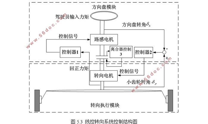
Finally, there is a structural theoretical analysis for the controller module, due to analysis of the implementation of the module and the steering wheel module, this paper will use the 2-wire steering control channel structure ,whose forward channel and the feedback channel respectively has only a single angle or torque information but its advantages include simple control structure and the better stability compared to multi-channel control structure. The forward channel is the difference between the pinion angle signal and steering wheel angle as a control signal to control the steering motor to achieve automobile steering control; the feedback channel is by turning reactive torque control as the basis for controlling the motor road feel to achieve a sense of driver feedback.
Key WordsЃКSteering-By-Wire SystemЃЛPMDC motorЃЛPID controlЃЛControl Structure
ЛњаЕзЊЯђЦїЕФжївЊВЮЪ§
ВЮЪ§ ВЮЪ§жЕ
РраЭ ГнТжГнЬѕ
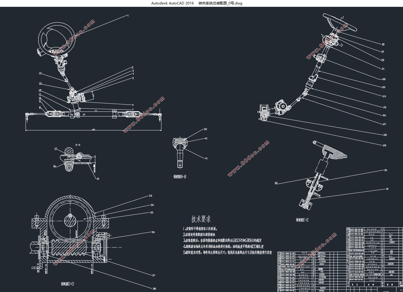
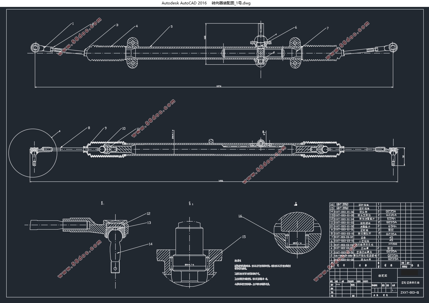
ДЋЖЏБШ 49.93mm/rev
ГнЬѕааГЬ 240mm
зюДѓГнТжСІ 6500N
ГнТжГнЬѕЪНзЊЯђЦїНсЙЙМђЕЅЁЂНєДеЃЌжЪСПЧсЃЌИеЖШДѓЃЌзЊЯђСщУєЃЌжЦдьШнвзЃЌГЩБОЕЭЃЌе§ЁЂФцаЇТЪЖМКмИпЃЌЖјЧвЪЁТдСЫзЊЯђвЁБлКЭзЊЯђжБРИЫЃЌЪЙзЊЯђДЋЖЏЛњЙЙМђЛЏЃЌЬиБ№ЪЪКЯгыжђЪНКЭТѓИЅбЗаќМмХфгУ[3]ЃЌвђДЫБОЮФПМТЧЕНдГЕаЭЧАаќМмНсЙЙвдМАТњзуЯпПизЊЯђвЊЧѓЙЪВЩгУГнТжГнЬѕЪНзЊЯђЦїЁЃ

ФПТМ
еЊ вЊ I
Abstract II
ФПТМ I
Ек1еТ аїТл 1
1.1ЩшМЦБГОАМАвтвх 1
1.2ЦћГЕзЊЯђЯЕЭГЕФЗЂеЙЯжзД 2
1.2.1 ЙњЭтЯпПизЊЯђЯЕЭГЕФЗЂеЙЯжзД 2
1.2.2 ЙњФкЯпПизЊЯђЯЕЭГЗЂеЙЯжзД 2
1.3 ЯпПизЊЯђЯЕЭГЕФИХЪі 3
1.4 БОЮФбаОПФкШн 5
Ек2еТ ЯпПизЊЯђЯЕЭГзЊЯђжДааФЃПщЩшМЦ 7
2.1зЊЯђжДааФЃПщзщГЩ 7
2.1.1ЛњаЕзЊЯђЦї 7
2.1.2зЊЯђжДааЕчЛњ 8
2.1.3МѕЫйЦїбЁаЭ 11
2.1.4ДЋИаЦїбЁаЭ 12
2.2зЊЯђжДааЕчЛњФЃаЭЕФНЈСЂ 13
2.2.1зЊЯђСІОиЕФПижЦЗНЗЈ 14
2.2.2зЊЯђжДааЕчЛњзЊОиПижЦЗТецЗжЮі 18
2.3ЯпПизЊЯђЯЕЭГФЃаЭЩшМЦ 20
2.3.1ЦћГЕзЊЯђФЃаЭНЈСЂ 20
2.3.2зЊЯђЗТецФЃаЭДюНЈ 22
2.3.3зЊЯђЯЕЭГЗТецЗжЮі 23
2.4БОеТаЁНс 26
Ек3еТ ЯпПизЊЯђЯЕЭГШпгрЯЕЭГФЃПщЩшМЦ 27
3.1ЯпПизЊЯђЯЕЭГШпгрЩшМЦЬсГі 27
3.2ВЛЭЌЯпПизЊЯђЯЕЭГШпгрЯЕЭГНсЙЙМАдРэ 27
3.2.1вКбЙзЊЯђШпгрЩшМЦ 27
3.2.2ЛњаЕзЊЯђШпгрЩшМЦ 28
3.2.3ЯпПизЊЯђШпгрЩшМЦ 29
3.3ЯпПизЊЯђЯЕЭГШпгрЩшМЦНсЙЙ 29
3.4БОеТаЁНс 31
Ек4еТ ЯпПизЊЯђЯЕЭГЗНЯђХЬФЃПщЩшМЦ 32
4.1ЗНЯђХЬФЃПщНсЙЙ 32
4.1.1ТЗИаЕчЛњ 32
4.1.2ДЋИаЦїбЁаЭ 34
4.2ТЗИаЫуЗЈФЃаЭЩшМЦ 35
4.2.1ТЗИаМђЪі 35
4.2.2Лие§СІОиМЦЫу 35
4.2.3ТЗИаЫуЗЈЗТецЗжЮі 38
4.3БОеТаЁНс 41
Ек5еТ ЯпПизЊЯђЯЕЭГзмПижЦНсЙЙЩшМЦ 42
5.1ЯпПизЊЯђЯЕЭГПижЦНсЙЙ 42
5.2 ЯпПизЊЯђЯЕЭГзмПижЦНсЙЙ 43
5.3БОеТаЁНс 44
Ек6еТ ШЋЮФзмНсгыеЙЭћ 45
6.1ШЋЮФзмНс 45
6.2баОПеЙЭћ 46
ВЮПМЮФЯз 47
ИНТМ 49
жТаЛ 50
|