轻型客车驱动桥总成三维设计(含CAD零件图装配图,CATIA三维图)(论文说明书16000字,CAD图8张,CATIA三维图)
摘要
本文以轻型客车驱动桥为研究对象,运用逆向工程的理论和方法,得到了驱动桥的模型并进行装配,达到了三维设计的目的。以下是本次设计中进行的工作:
对各个驱动桥零件进行三维激光扫描。这是逆向工程技术的第一个步骤,在本次设计中,三维激光扫描使用的工具是Handy Scan 3D三维激光扫描仪,该扫描仪使用的测量原理是光学三角法。在扫描过程中,灵活运用了微反光点及辅助板以提高扫描效率与扫描准确度,最终完成了对驱动桥20个零件的扫描工作。
对扫描获得的驱动桥点云数据进行处理。点云数据处理是为了使点云能够符合接下来建模工作的要求,本次设计使用的点云处理软件是Geomagic Studio软件。在处理过程中,对一些无用点进行了剔除,对一些由于震动等原因形成的噪点进行了降噪处理,对一些扫描缺失的地方,进行了点云补充,这些都为接下来的建模工作打下了良好的基础。
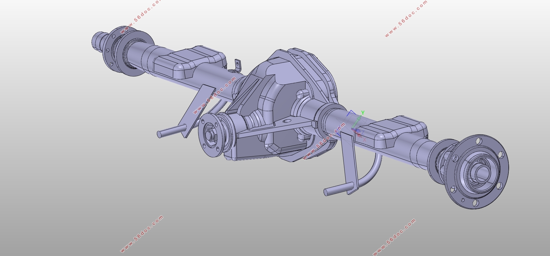
对处理好的点云进行网格化进而逆向建模。逆向建模工作是整个逆向工程过程中最复杂也是最耗时的一个环节,本次设计使用的建模软件是CATIA。在建模过程中,首先在逆向点群编辑中导入igs格式的点云,并将其网格化,接着建立基准,在此基础上创建曲面进行修剪接合等指令,最后创建出实体。几乎所有的建模步骤都是这样的基本步骤,灵活运用创成式与零件设计,最终完成驱动桥零件的逆向建模。
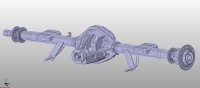
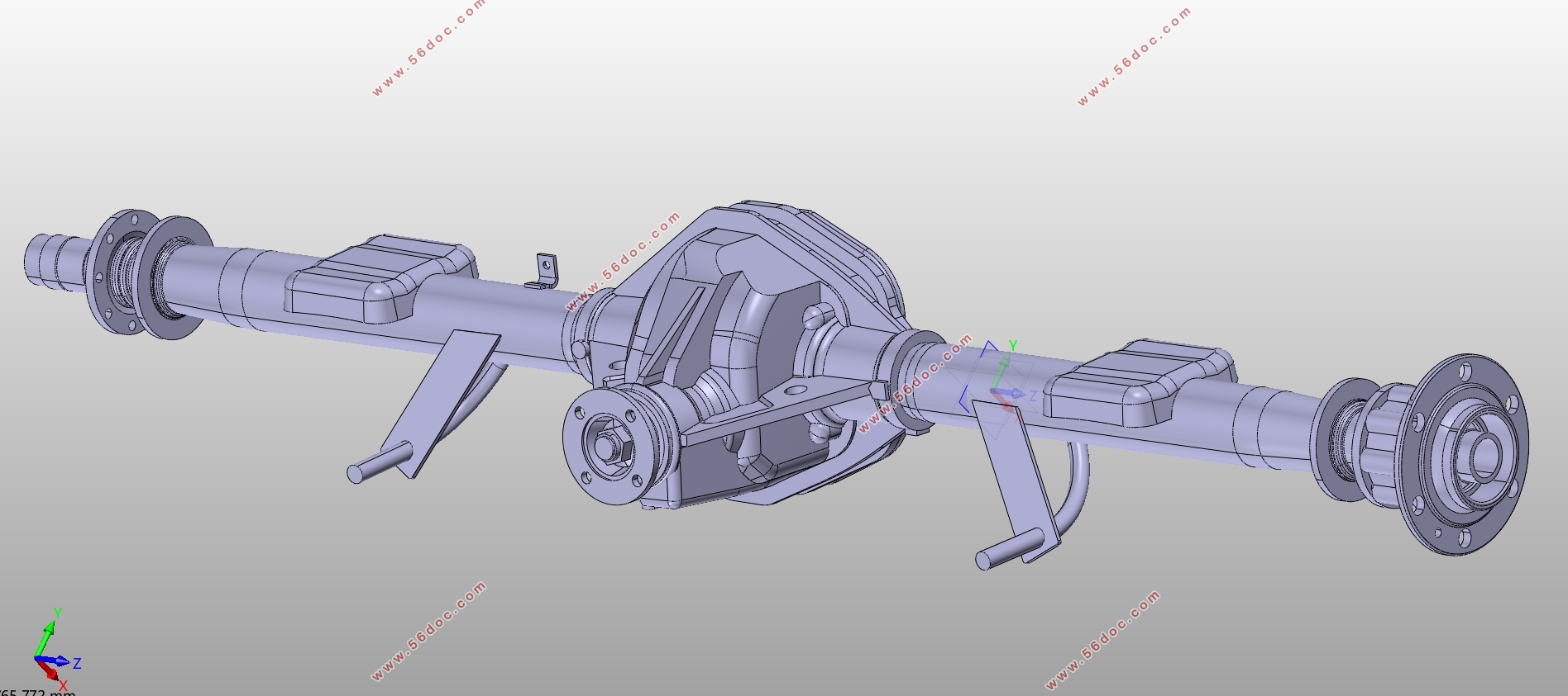
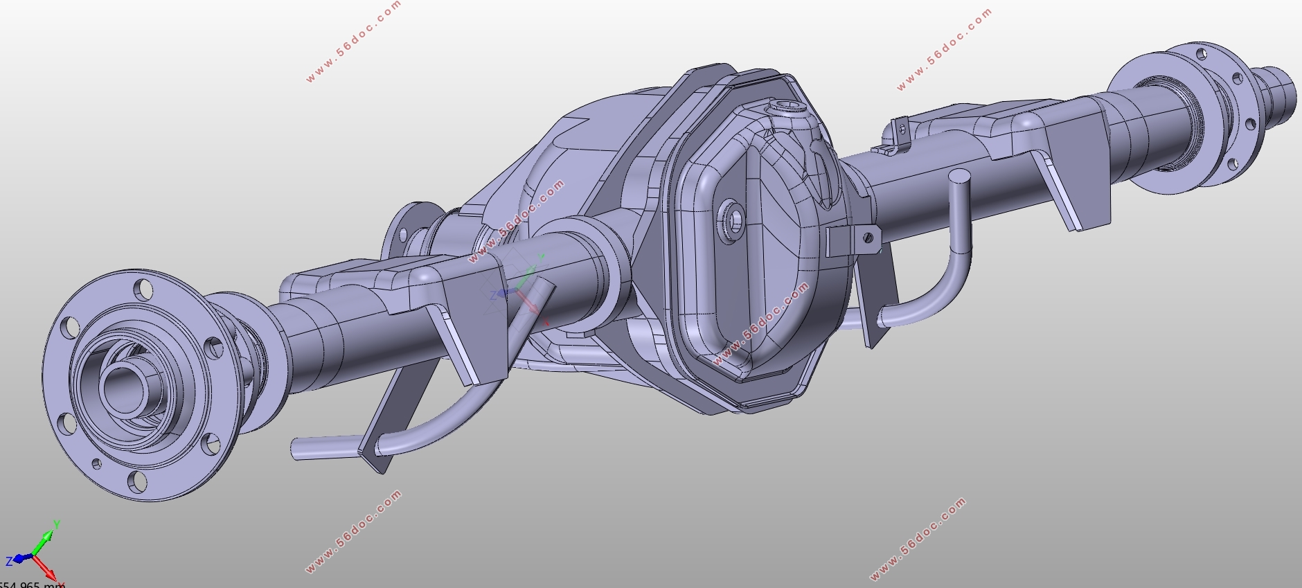
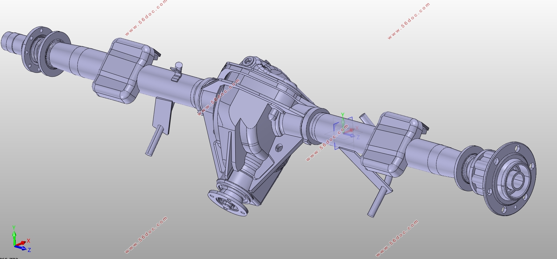
对驱动桥模型进行装配设计。与建模相同,装配设计仍在CATIA中进行。装配能够将各零件之间的相对位置显示出来,并在此基础上可以检测零件以及约束的合理性。在本次设计中,导入第一个驱动桥零件,约束其固定,接着一个一个导入零件并使用相合约束、接触约束、相离约束等约束其在正确的位置,这为接下来的二维图设计打下了基础。
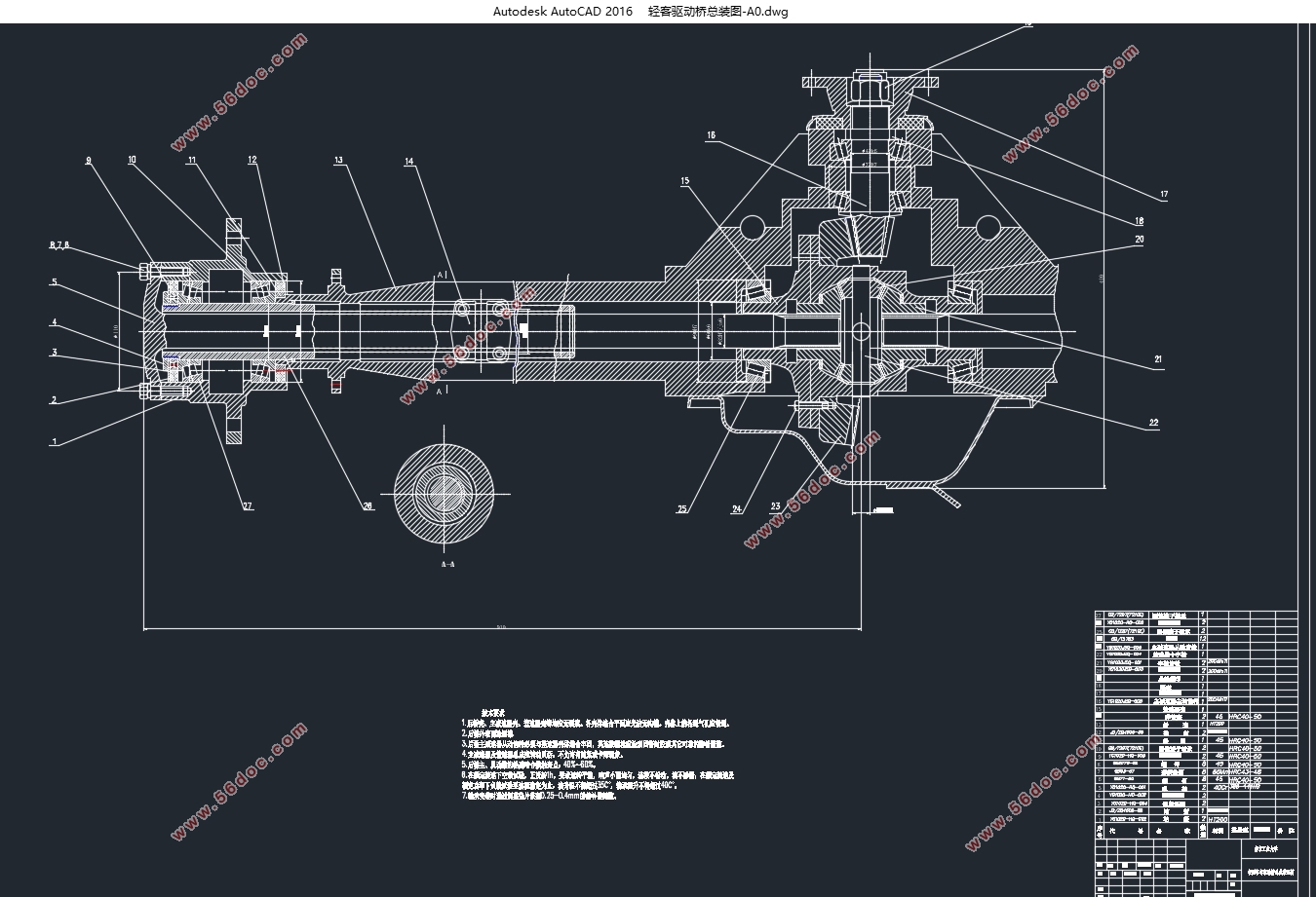
对驱动桥模型进行二维图设计。二维图因为公差的原因,可以说是三维模型与产品之间的桥梁,本次设计的二维图设计是在CAD中进行的。二维图是从CATIA中导出,再进入CAD中进行齿轮部分优化以及尺寸的标注的,最后完成了主减速器主、从动齿轮的零件图,半轴与差速器的总成图以及驱动桥的装配图。至此算是初步完成了三维设计的工作。
关键词:逆向工程 CATIA 逆向建模 CAD 二维图
Three dimensional design of the drive bridge assembly of light bus
Abstract
This paper takes the driving bridge of light bus as the research object, and get the model of the drive bridge and assemble by the theory of reverse engineering to achieve the goal of the three-dimensional design. The following is the work carried out in this design:
Three dimensional laser scanning of each drive axle part. This is the first step in reverse engineering. In this design, the tool used for 3D laser scanning is the Handyscan 3D three-dimensional laser scanner. The scanner uses the optical triangulation method. During the scanning process, the micro reflector and auxiliary board are used flexibly to improve the scanning efficiency and the scanning accuracy. Finally, the scanning work of the 20 parts of the driving bridge is completed.
The data of the driving bridge's point cloud are scanned. Point cloud data processing is to make point cloud meet the requirements of next modeling work. The point cloud processing software used in this design is Geomagic Studio software. In the process of processing, some useless points are eliminated, noise reduction is done to some noise caused by vibration and other reasons. Some places with missing scan are supplemented by point clouds, which have laid a good foundation for the next modeling work.
Grid points are processed and inverse models are processed. Reverse modeling is the most complex and time-consuming part of the whole reverse engineering process. The modeling software used in this design is CATIA. In the process of modeling, first, the point cloud of IGS format is introduced into the editors of the reverse point group, and then it is meshed, then the datum is set up. On this basis, the surface is created to trim and join the instructions. Finally, the entity is created. Almost all modeling steps are such basic steps, flexible use of generative and part design, and ultimately complete reverse modeling of drive axle parts.
The assembly design of the drive bridge model is carried out. The same as modeling, assembly design is still carried out in CATIA. Assembly can display the relative position between parts, and on this basis, it can detect the rationality of parts and constraints. In this design, the first part of the drive bridge is introduced, which is bound to its fixed position, and then a part is introduced and the matching constraint, contact constraint, and separation constraint are used to restrain it in the correct position, which lays the foundation for the next two-dimensional graph design.
The two dimensional diagram of the drive bridge model is designed. The two-dimensional diagram is a bridge between the three-dimensional model and the product because of the tolerance. The two-dimensional design of the design is carried out in CAD. The two-dimensional graph is derived from the CATIA, and then into the CAD for gear partial optimization and dimensioning. Finally, the part drawing of the main and driven gear of the main reducer, the assembly diagram of the half shaft and the differential and the assembly drawing of the drive bridge are completed. At this point, we have preliminarily completed the work of three-dimensional design.
Keywords: Reverse engineering CATIA Reverse modeling CAD 2D drawing
目录
摘要 I
ABSTRACT II
第一章绪论 1
1.1课题研究的意义 1
1.2国内驱动桥的发展现状 2
1.2.1 以测绘和引进为主的开发模式 2
1.2.2 自主研发的开发模式 2
1.2.3 驱动桥壳常规设计方法 2
1.3国外驱动桥设计的发展现状 3
1.3.1 模块化技术的采用 3
1.3.2 模态分析 3
1.3.3 配置高性能制动器的驱动桥技术 3
1.4本章小结 4
第二章三维设计的理论基础 5
2.1逆向工程 5
2.1.1逆向工程概述 5
2.1.2逆向工程主要技术 5
2.1.3逆向工程实施条件 6
2.2三维激光扫描技术 6
2.2.1三维激光扫描技术的基本原理 6
2.2.2三维激光扫描技术的工程应用 7
2.3三维扫描 7
2.3.1前期准备 7
2.3.2扫描过程 8
2.4点云处理 8
2.5建模工具 9
2.5.1零件设计 9
2.5.2创成式曲面设计 10
2.5.3装配设计 10
2.5.4二维工程制图 10
2.5.5逆向点群编辑 10
2.6驱动桥设计的相关公式 10
2.6.1主减速器设计 11
2.6.2差速器设计 13
2.7本章小结 15
第三章轻型客车驱动桥三维建模设计 16
3.1差速器壳体建模 16
3.1.1点云的导入与三角网格化 16
3.1.2建立旋转体中心轴和切割平面 17
3.1.3旋转体的建立 18
3.1.4各部分实体特征的创建 20
3.2行星齿轮 23
3.3本章小结 25
第四章轻型客车驱动桥总成装配与两维工作图设计 26
4.1装配设计 26
4.1.1装配设计界面介绍 26
4.1.2 差速器的装配 27
4.2二维图的建立 30
4.2.1视图的选择 30
4.2.2半轴总成图的建立 30
4.2.3其余二维图的设计 31
4.3逆向工程的经济性分析 34
4.4本章小结 35
第五章总结与展望 36
5.1总结 36
5.2展望 36
参考文献 38
致谢 39
|