东风K74M商用车转向系统设计(含CAD零件图装配图)(任务书,开题报告,文献摘要,论文说明书15000字,CAD图纸6张)
摘要:
在驾驶员驾驶的过程中,车辆需要按照人的意愿经常改变其行驶方向。也就是所谓汽车转向[1]。而使其实现的这一套机构,称为汽车转向系统。本文的研究内容为东风K74M商用汽车转向系统的设计。
本文针对液压动力转向技术在商用车方面的应用并加以改进,设计出一款应用于商用汽车上的液压助力转向系统。本文通过对汽车转向系统技术的发展经历和液压助力转向技术的发展现状和最新的研究成果进行了分析,结合汽车设计和机械原理的知识,设计出了一款适用于东风K74M转向的液压转向系统,并详细介绍了该系统的设计方案。首先选择转向器转向传动机构,接着设计转向器,转向传动机构和助力转向机构。
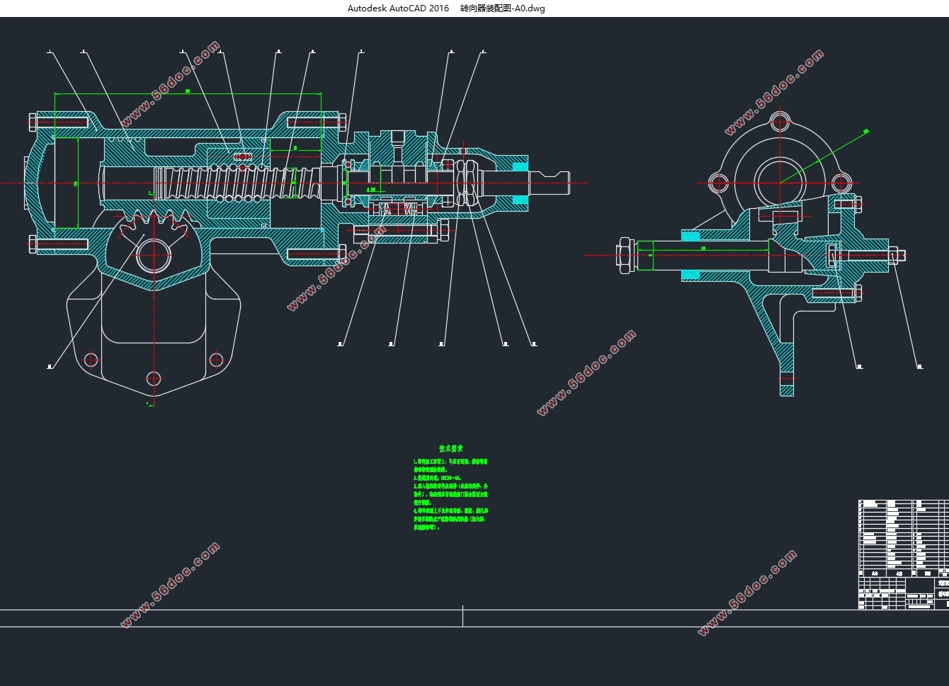
方向机在设计中选用为循环球齿条齿扇式,在对方向机的设计中,对螺杆传动副的设计以及齿扇传动副进行了设计。
转向梯形结构则选用的是整体式转向梯形,本文在设计中借鉴了同类汽车转向梯形设计的经验尺寸对转型梯形进行尺寸的初选。再通过图解法来判定设计的转向梯形结构是否符合基本要求。
本文在学习,借鉴,归纳,总结前人的成果上,对所设计转向系统的机械部分进行理论分析,设计和优化。为东风K74M商用车转向系统的设计提供了一种步骤较为简单的设计方法。
关键词:转向系统 转向器 转向梯形 结构元件
ABSTRACT
In the process of driving a car, it is necessary to constantly change its driving direction according to the driver's wishes. That is, the so-called car steering. When the vehicle is driving in a straight line, the steering wheel is often affected by the lateral interference force of the road surface and automatically deflected to change the direction of travel. At this time, the driver can also use this set of mechanisms to deflect the steering wheel in the opposite direction, so that the car can return to the original driving direction. This set of institutions is called the automobile steering system. The research content of this paper is the design of the Dongfeng K74M commercial vehicle steering system.
In this paper, the application of hydraulic power steering technology in commercial vehicles is improved and an electric hydraulic power steering system applied to commercial vehicles is designed. This article analyzes the development experience of automobile steering system technology and the development status and latest research results of electro-hydraulic power steering technology. Based on the knowledge of automobile design and mechanical principles, a hydraulic steering system suitable for steering of Dongfeng K74M is designed. System, and detailed description of the design of the system. Firstly, the steering gear transmission mechanism of the steering gear is selected, and then the steering gear, the steering transmission mechanism and the assisting system are designed.
In the design of the steering gear, the recirculating ball rack and pinion steering gear is selected. In the design of the steering gear, the design of the screw-steel ball-nut transmission pair and the design of the rack-tooth-gear transmission pair are included.
The steering trapezoidal structure used in the design is a monolithic steering trapezoid. In this paper, we use the experience dimension of the steering trapezoidal design of the same type of
automobile to make a preliminary selection of the size of the transition trapezoid. Then through the graphical method to determine whether the design of the steering ladder structure meets the basic requirements.
This article, based on the study, reference, induction and summary of previous achievements, carries out theoretical analysis, design and optimization of the mechanical part of the designed steering system.
Keywords: Steering system Steering gear Steering trapezoidal structural elements

目录
摘要: 7
ABSTRACT 8
第一章 绪论 10
1.1转向系统概述 10
1.2汽车转向系统现状和发展趋势 10
1.2.1机械式转向系统 11
1.2.2机械式液压助力转向系统 11
1.2.3电动液压助力转向 11
1.2.4电动助力转向 12
1.2.5线控转向系统 12
1.3东风K74M转向系统设计主要内容 13
第二章 汽车转向系总体规划 13
2.1 转向系中一些关键的参数 13
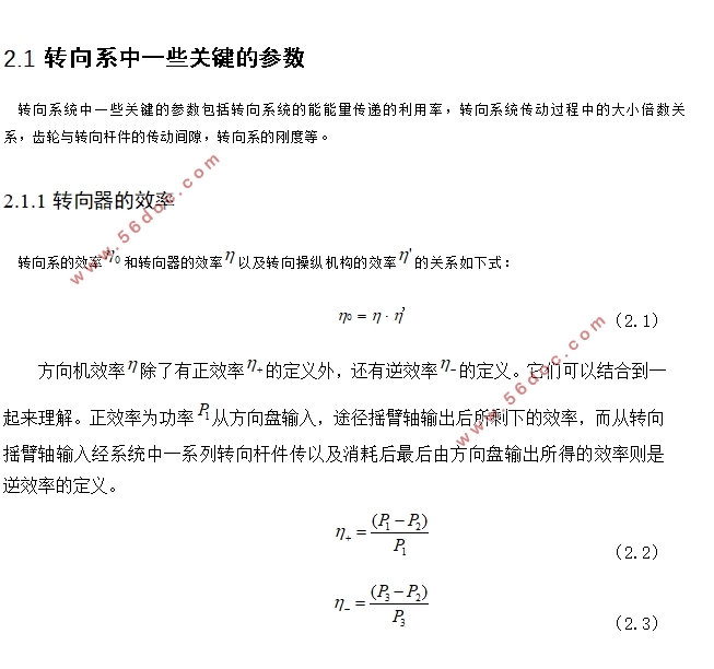
2.1.1转向器的效率 13
1.转向 14
2. 转向 14
2.1.2 传动比的变化特性 15
1.转向系传动比 15
2.转向系各种传动比之间的联系 15
3.转向系 16
4.转向器角传动比及其变化规律 16
2.1.3转向器传动副的传动间隙 17
2.1.4转向盘的总转动圈数 17
2.2转向系的选择 17
2.2.1MS系统 17
2.2.2PS系统 18
1.液压式动力转向机构 19
2.车速感应型动力转向机构 19
2.3 本章小结 20
第三章 汽车转向器方案设计 20
3.1机械式转向器的选择 20
3.1.1齿轮齿条式转向器 20
3.1.2循环球式转向器 20
第4章 汽车转向传动机构的方案选择与设计 21
4.1转向传动机构的设计 21
4.1.1汽车采用非独立悬架时选择的转向传动机构 21
1.转向传动机构的组成 21
2.转向摇臂 22
3.转向直拉杆 22
4.转向横拉杆 22
4.1.2汽车采用独立悬架时选择的转向传动机构 22
4.2转向梯形的选择 22
4.2.1整体式转向梯形 23
4.2.2断开式转向梯形 23
4.3本章小结 24
第五章 转向系的设计计算 24
5.1转向器的结构型式选择及其设计计算 24
5.1.1传动副的设计 24
(1)钢球中心距D、螺杆外径D1和螺母内径D2 24
(2)钢球直径d及数量n 25
(3)滚道截面 25
5.1.2齿条、齿扇传动副的设计 27
30
5.1.3转向器校核 30
5.1.4循环球式转向器零件强度计算 31
(1)钢球与滚道间的接触应力 31
(2) 33
第六章 动力转向系的设计计算 33
6.1 对动力转向机构的要求 34
6.2 动力转向机构布置方案的选择 34
6.2.1 动力转向形式与结构方案 34
6.2.2 传能介质的选择 35
6.2.3 液压转向加力装置的选择 35
6.2.4 液压转向加力装置转向控制阀的选择 36
6.3 动力缸的设计计算 36
6.3.1 刚径尺寸Dc的计算 36
6.3.2 活塞行程s的计算 38
6.3.3 动力缸壁厚t的计算 38
6.4 分配阀的参数选择与设计计算 39
6.4.1 预开隙 39
6.4.2 滑阀总移动量 40
6.4.3 局部压力降 40
6.4.4 油液流速的允许值[v] 40
6.4.5 滑阀直径d 40
6.4.6 滑阀在中间位置时的油液流速v 40
6.4.7 分配阀的泄漏量 41
6.5 回位弹簧的预紧力和反作用阀直径的确定 41
6.6 油泵排量与油罐容积的确定 42
第七章转向传动机构设计 42
7.1整体式转向梯形结构优化设计 43
7.2 转向操纵机构的防伤安全措施 45
7.3本章小结 45
结 论 46
致谢 47
参考文献 48
|