越野车分动器结构设计(含CAD零件图装配图)(英文版)
来源:56doc.com 资料编号:5D25283 资料等级:★★★★★ %E8%B5%84%E6%96%99%E7%BC%96%E5%8F%B7%EF%BC%9A5D25283
资料以网页介绍的为准,下载后不会有水印.资料仅供学习参考之用. 密 保 惠 帮助
资料介绍
越野车分动器结构设计(含CAD零件图装配图)(英文版)(任务书,开题报告,文献摘要,外文翻译,论文说明书英文版8000字,CAD图纸5张)
Abstract
Off-road vehicles often need to run in bad roads even without roads which is especially worse for military vehicles. This requires an increase in the number of driving wheels, thusoff-road vehicles usuallyusemulti-axis drive.
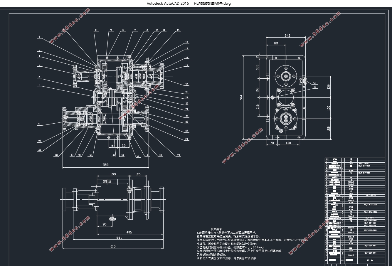
The function of the transfer case is to distribute the power output to the drive axle and further increase the torque. The transfer case is also a gear transmission system which is fixed on the frame separately. The input shaft is connected with the output shaft of the transfer case by universal transmission device while the output shaft of the transfer case has a number of axes, which are respectively connected with each drive axle by the universal transmission device.
This paper mainly discusses the design process, selection of structural scheme, main parameters, gear design, shaft design,calculation and checking, design of other structural components through the research and design of a specific type of off-road vehicle transfer case.
Keywords:transfer case; triaxial type; gear; shaft; gear drive; check
Design initial data
Maximum speed: 80Km/h
Rated power of transfer case: 40KW
Torque: 353 N.m
Preparation quality: 5320Kg
Maximum input speed: 3000r / min
Minimum input speed: 600r / min

Abstract 1
Chapter 1 Theory 1
1.1Overview 1
1.1.1 Design requirements for transfer case 1
1.1.2 Type of transfer case 1
1.1.3 Development of transfer case 3
1.1.4 Working principle and function of the transfer case 5
1.2 Purpose and significance of the study 5
1.3 Research methods 6
Chapter 2 Selection and calculation of the main parameters and structure of the transfer case 7
2.1 Design initial data 7
2.2 Determination of the high and low transmission ratio of the transfer case 7
2.3 Determination of shunt drive scheme 8
2.4 Shift structure form 9
2.5 Structure of shafts and gears 10
2.5.1 Shaft structure 10
2.5.2 Arrangement of gears 11
2.6 Determination of central distance A 12
2.7 Gear parameters 13
2.7.1 Module 13
2.7.2 Pressure angle 13
2.7.3 Spiral angle 13
2.7.4 Tooth width 14
2.7.5 Coefficient of tooth top height 14
2.8 Summary of this chapter 14
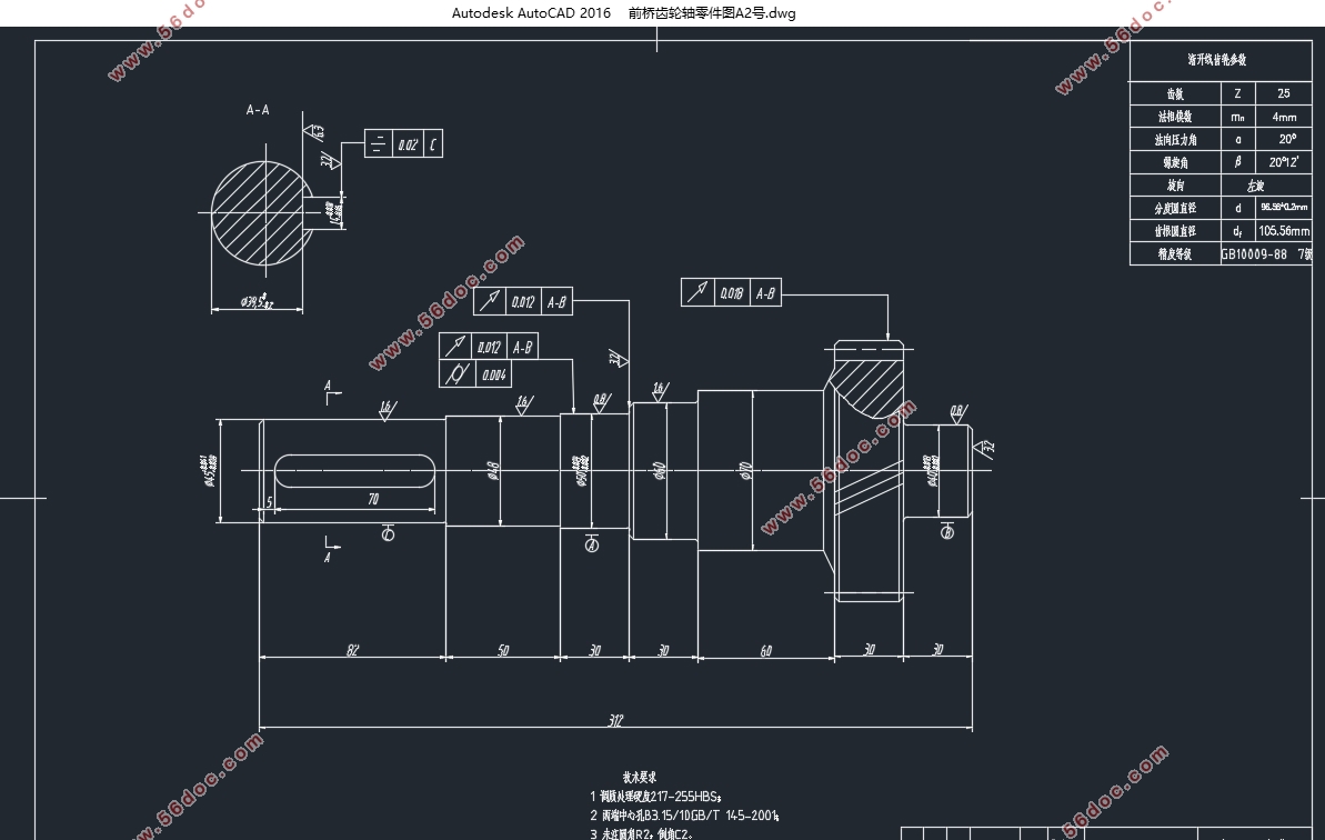
Chapter 3 Design calculation and checking of Gear 15
3.1 Design and calculation of Gear 15
3.1.1 Distribution of the number of teeth of each gear 15
3.1.2 Calculation of parameters for each gear 17
3.1.2 Selection principle of gear materials 19
3.1.3 Calculation of torque for each shaft 20
3.2 Checking of gear teeth 20
3.2.1 checking of contact strength of wheel teeth 20
3.2.2 Check of tooth root bending strength 21
3.3 Summary of this chapter 22
Chapter 4 Design and calculation of shafts and selection and checking of bearings 23
4.1Design calculation of Shaft 23
4.1.1 primary Shaft size 23
4.1.2 Form and size of spline 23
4.1.3 Shaft structure 24
4.2 Check of Shaft 26
4.3 Summary of this chapter 29
Chapter 5 process Analysis 30
5.1 The selection of the structural parts of the splitter 30
5.1.1Meshing sleeve calculation 30
5.1.2 Splitter shell 30
5.2 Process analysis 30
5.2.1 Shell processing technology 30
5.2.2 Gear processing technology 31
5.2.3 Processing Technology of Shaft 31
5.2.4 Assembly assembly 32
5.3 Summary of this chapter 32
Reference 33
Thanks 34
|