燃料电池客车后独立悬架设计(含CAD零件图装配图,CATIA三维图)(任务书,开题报告,文献摘要,外文翻译,论文说明书10000字,CAD图7张,CATIA三维图)
摘要
后悬架设计是汽车设计过程中相当重要的一个环节,在燃料电池客车后悬架设计中,它是车架与车桥之间的传力连接装置,可以把路面作用于车轮上的垂直反力、纵向反力和侧向反力以及由这些反力所造成的力矩传递到车架上,缓冲路面冲击,以保证车辆的行驶平顺性。
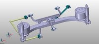
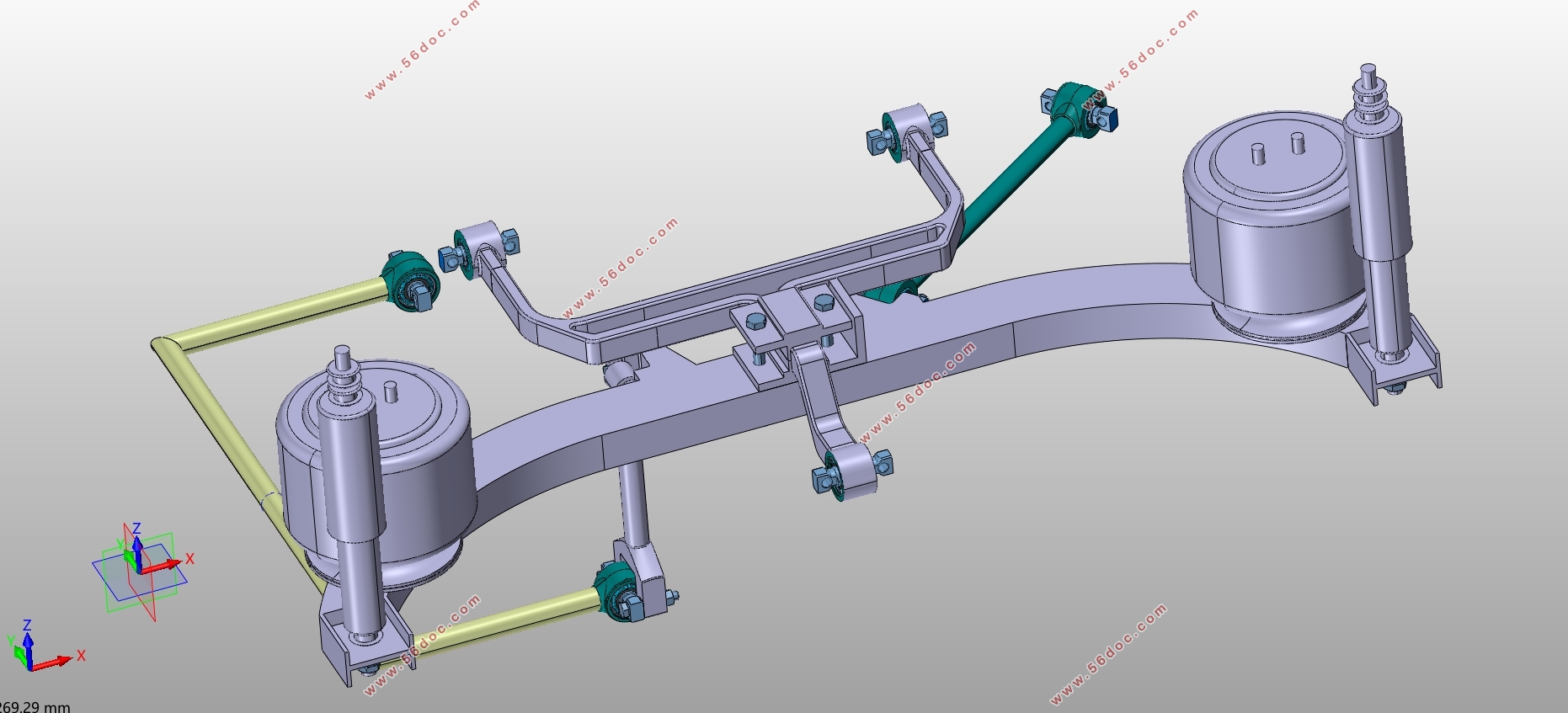
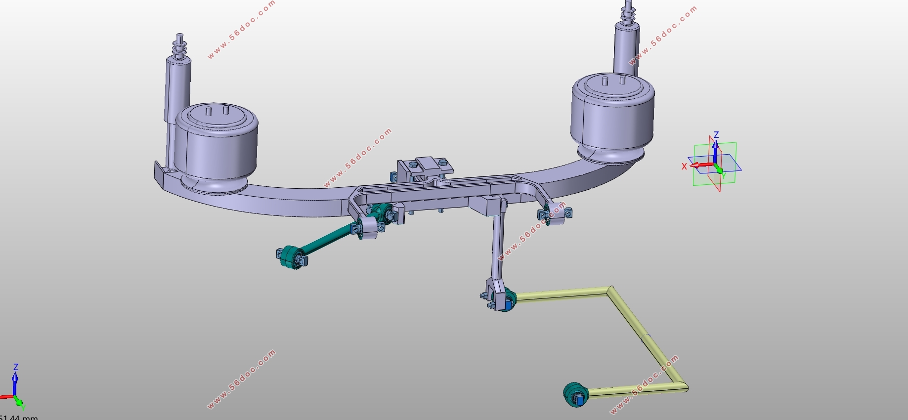
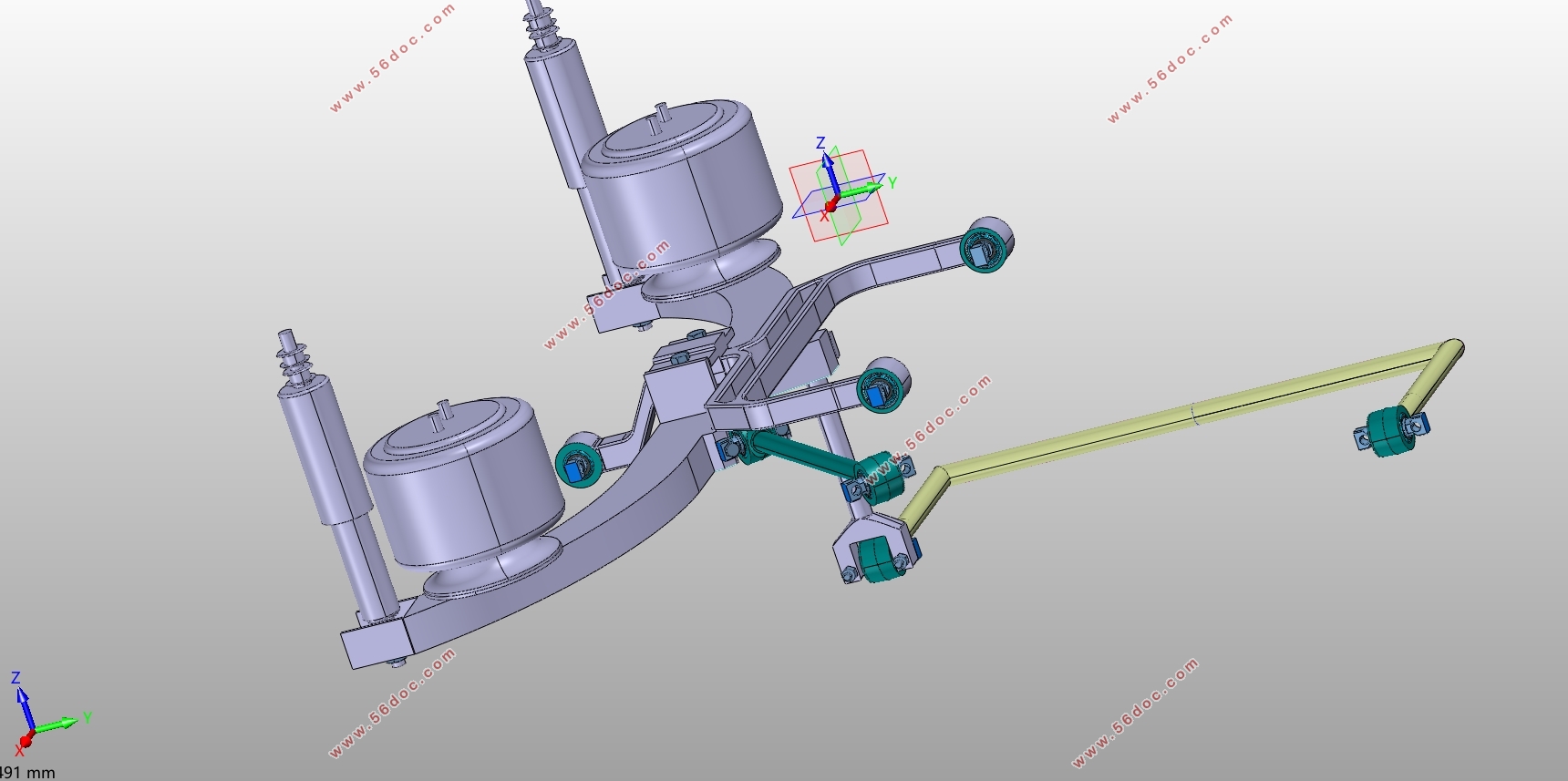
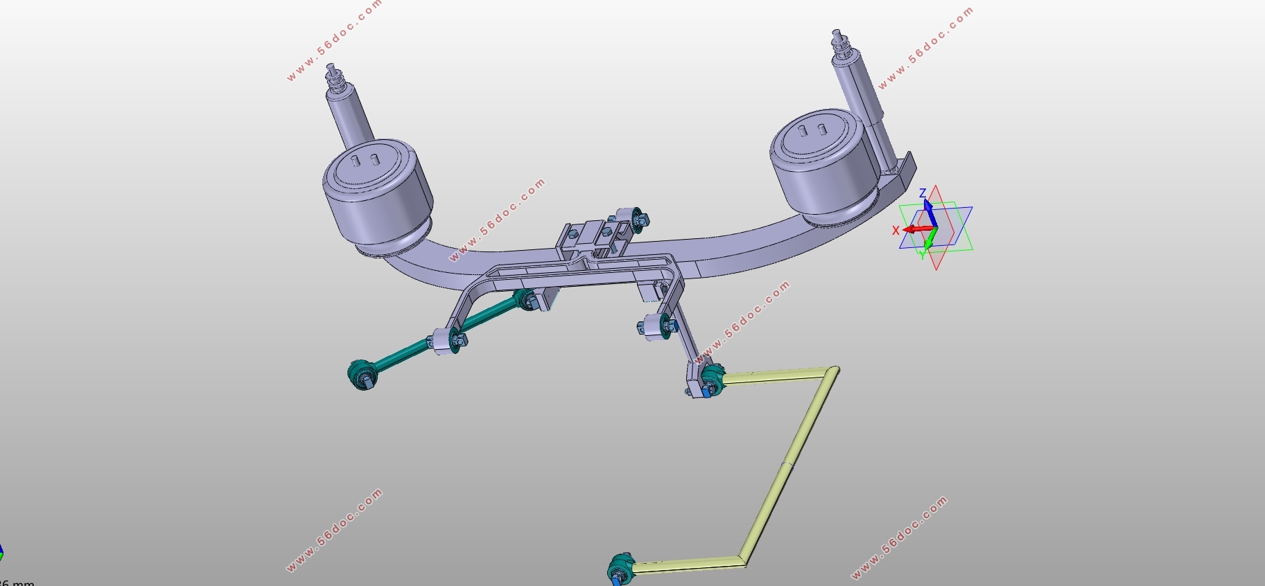
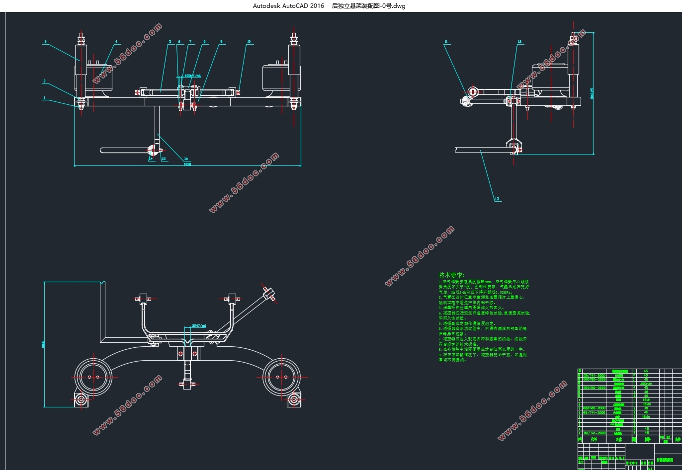
本文设计的是燃料电池客车的后悬架系统,主要由以下部分组成:膜式空气弹簧、双筒液力式减振器、c型梁、推力杆等组成。将四个空气弹簧和四个减振器分别安装在车轮两边的两个c型梁上,这样可以增加空气弹簧的簧距,然后将空气弹簧通过从车架伸出来的结构上,最终将c型梁固定连接在悬架摆臂上,然后通过导向机构将悬架及车架连接成一个整体。
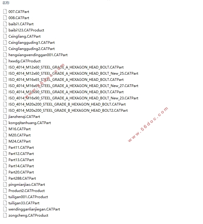
本文首先对空气悬架的优势及国内外的发展情况进行了综述,然后在选型方面选择了独立悬架的结构。随后就是对整体结构进行全面的设计计算,随后对其中一些部件进行强度计算,得到其结构,然后将设计的结构通过CATIA软件进行建模,得到最终结构后,将模型导出二维图,得到最终的设计图纸。
本文特色:本文设计的结构为空气悬架,并且是独立悬架结构,是一种相对于我们国家商用车比较新的结构。
关键词:空气悬架;独立悬架;客车;三维建模
ABSTRACT
The rear suspension design is a very important part of the automobile design process. In the rear suspension design of the fuel cell bus, it is a force connecting device between the frame and the bridge. It can transfer the surface of the road to the vertical, longitudinal and lateral forces on the wheel and the torque caused by these counterforces to the frame. Cushion the impact of the road to ensure the ride comfort of the vehicle.
The rear suspension system of fuel cell bus is designed in this paper, which consists of the following parts: the membrane air spring, the dual cylinder hydraulic damper, the C beam, the thrust rod and so on. Four air springs and four shock absorbers are mounted on two C beams so that the spring distance of the air spring is added to the wide range of the car, then the air spring is installed on the four branches that are extended at both ends of the frame. The C beam is mounted on the arm of the pendulum, and the suspension and the frame form a whole by the guiding machine.
In this paper, the advantages of air suspension and the development at home and abroad are summarized firstly, then the structure of independent suspension is selected. Then the overall structure is designed and calculated. Then some of the components are calculated and the structure is obtained. Then the design structure is modeled by CATIA software. After the final structure is obtained, the model is derived from the two-dimensional diagram and the final design paper is obtained.
This article features: the structure designed in this paper is air suspension, and is an independent suspension structure. It is a new structure compared with our commercial vehicle.
Key words: air suspension; independent suspension; passenger car; 3D modeling
本文主要研究内容
本文主要以燃料电池客车后悬架作为研究设计对象,通过对现有的各种空气悬架结构进行了解以后,对燃料电池客车进行设计并建立模型。主要内容有:
(1)燃料电池客车的后悬架选型;
(2)选择后悬架的性能参数;
(3)对后悬架结构进行设计计算;
(4)通过CATIA软件生成模型;
(5)通过ANSYS进行应力分析;
(6)利用auto cad绘制总成及主要零件图。
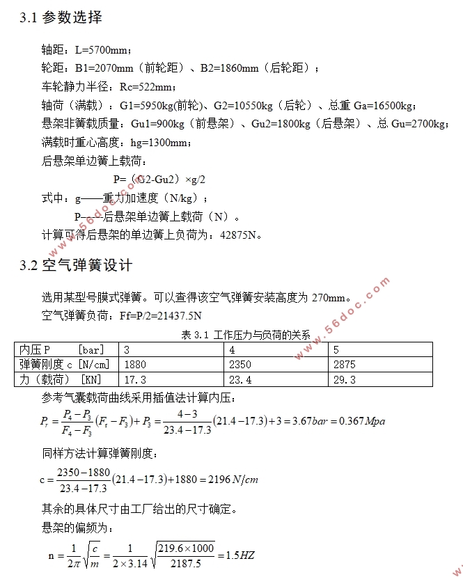
参数选择
轴距:L=5700mm;
轮距:B1=2070mm(前轮距)、B2=1860mm(后轮距);
车轮静力半径:Rc=522mm;
轴荷(满载):G1=5950kg(前轮)、G2=10550kg(后轮)、总重Ga=16500kg;
悬架非簧载质量:Gu1=900kg(前悬架)、Gu2=1800kg(后悬架)、总Gu=2700kg;
满载时重心高度:hg=1300mm;
后悬架单边簧上载荷:
P=(G2-Gu2)×g/2
式中:g——重力加速度(N/kg);
P——后悬架单边簧上载荷(N)。
计算可得后悬架的单边簧上负荷为:42875N。
3.2空气弹簧设计
选用某型号膜式弹簧。可以查得该空气弹簧安装高度为270mm。
空气弹簧负荷:Ff=P/2=21437.5N
表3.1 工作压力与负荷的关系
内压P [bar] 3 4 5
弹簧刚度c [N/cm] 1880 2350 2875
力(载荷) [KN] 17.3 23.4 29.3
目录
第一章 绪论 4
1.1研究目的 4
1.2研究意义 4
1.3国内外研究现状 5
1.4本文主要研究内容 6
第二章 燃料电池客车后悬架的结构选择 7
2.1悬架类型 7
2.2 空气悬架工作原理 8
2.3空气弹簧的选择 9
2.4减振器的选择 10
2.5本章小结 11
第三章 燃料电池客车后独立悬架设计 12
3.1参数选择 12
3.2空气弹簧设计 12
3.3减振器设计 13
3.4推力杆设计 14
3.5横向稳定杆设计 15
3.6其余构件 16
3.7本章小结 17
第四章 建立模型及ansys分析 18
4.1三维建模 18
4.2ANSYS分析 21
4.3本章小结 23
第五章 总结 24
致谢 25
参考文献 26
|