跨界车传动系统主减速器设计(含CAD零件图装配图)
来源:56doc.com 资料编号:5D25300 资料等级:★★★★★ %E8%B5%84%E6%96%99%E7%BC%96%E5%8F%B7%EF%BC%9A5D25300
资料以网页介绍的为准,下载后不会有水印.资料仅供学习参考之用. 密 保 惠 帮助
资料介绍
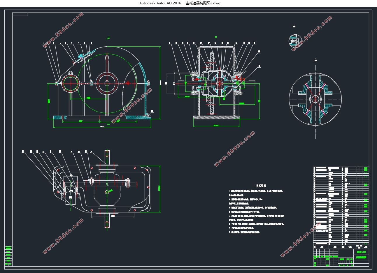
跨界车传动系统主减速器设计(含CAD零件图装配图)(任务书,开题报告,论文说明书13000字,CAD图15张)
摘要
目前市面上的轻型载货卡车的额定载重有1.8吨左右的,也有4吨左右的,为满足客户需求,急需开发一款载重为3吨左右的跨界轻卡来丰富商用车制造厂的产品阵营。本课题意在为此种跨界车型设计一款合适的主减速器。主减速器它是汽车传动系统里面很重要的组成部分,在提高汽车几大性能里面的行驶平顺性和通过性两个方面它有独特的作用。主减速器的主要工作原理是:通过齿数少的齿轮来带动齿数多的齿轮从而达到降低转速、增大力矩的目的,利用锥齿轮传动的主减速器还可以改变动力的传递方向,这对发动机纵置的汽车布置是很重要的,另外,在汽车转弯过程当中,主减里面的差速器能明显改善汽车操纵稳定性。
本文设计的是跨界轻型卡车主减速器,主要的工作内容为:主从动齿轮的设计,主减速器结构的选择,行星齿轮及半轴齿轮的设计,轴承的设计及校核,轴的设计及校核。然后根据计算结果得到的核心尺寸基于CATIA进行建模,并对整个装配部件基于CATIA DMU模块进行机械运动仿真从而验证设计的可行性。
关键词: 主减速器;跨界轻卡;CATIA建模;DMU运动仿真
Abstract
Currently, the light truck is rated at about 1.8 tons and 4 tons sold in the market. We are badly in need of a new one rated at about 3 tons to meet the customs’ different needs. Automotive main reducer is one of the main transmission components in automotive transmission system. Automobile main reducer has a unique performance in improving the car driving and differential stability and its trafficable characteristics, is one of the vital parts of automobile design. Automotive main reducer in the transmission lines use to decrease the vehicle speed and increase torque by relying on the gear with fewer teeth to drive the gear with more teeth more gear, it also used to change the driving force for the direction of transmission automobile. On the other hand, differential mechanism in the reducer do good to vehicle handling.
This paper is about automotive main reducer design for cross truck. The design work mainly include: the structure choose of main reducer, the design of master slave bevel gear, the design of planetary gear and axle shaft gear, bearings design and check, half shaft design and check. With the main sizes from calculating, building the main reducer’s models in CATIA, finally the principle of automotive main reducer is simulated and analyzed in CATIA DMU
Key words: Main reducer; Cross light truck; CATIA models building; DMU motion simulation


目录
1 引言 5
1.1国内外主减速器行业现状和发展趋势 5
1.2本设计的目的和意义 6
2 动力系统结构设计 7
2.1整车动力性能参数的选型 7
2.2主减速器传动比的计算 7
3 主减速器设计 8
3.1 主减速器概述 8
3.2 主减速器应满足基本要求 8
3.3 主减速器传动方案设计 9
3.3.1主减速器的齿轮类型 9
3.3.2主减速器的减速形式 10
3.3.3主减速器主、从动锥齿轮的支撑方案 11
3.4 斜齿圆柱齿轮的各主要参数选取和计算 12
3.4.1 齿轮材料及齿数的初步选择 12
3.4.2 斜齿轮的设计计算 12
3.5 主减速器箱体设计 17
4 差速器设计 19
4.1 普通锥齿轮式差速器齿轮设计 19
4.2 普通锥齿轮式差速器齿轮强度校核 22
5 轴及轴上零件设计 23
5.1 减速器主动齿轮轴设计 23
5.2 滚动轴承的选型与计算 26
5.2.1 主动齿轮轴承的选择 26
5.2.2 差速器壳体轴承的选择 27
5.2.3 半轴轴承的选择 27
5.3 主动齿轮轴上键的选择以及计算 28
5.4 半轴的设计及计算 28
6 主减速器的CATIA三维建模、装配及运动仿真 29
6.1 CATIA V5简介 29
6.2 主减速器零部件建模 30
6.2.1齿轮轴 30
6.2.2从动齿轮 31
6.2.3行星锥齿轮 32
6.2.4半轴齿轮 33
6.2.5行星齿轮轴 34
6.2.6差速器壳体 34
6.2.7差速器壳盖 35
6.2.8主减速器壳体底座 36
6.3 主减速器零部件装配 37
6.3.1差速器壳盖 37
6.3.3齿轮轴装配 39
6.3.4从动合件的装配 39
6.4 主减速器运动仿真 40
7 总结 44
参考文献 45
致谢语 46
|


