汽车摩擦片式防滑差速器设计(含CAD零件图装配图)(任务书,开题报告,文献摘要,外文翻译,论文说明书12000字,CAD图6张)
摘 要
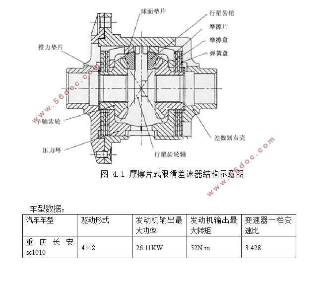
普通差速器已无法满足人们的需求,越来越多的汽车加装了防滑差速器,设计一种摩擦片式差速器,它是利用摩擦元件相对转动所产生的摩擦力矩来实现左右半轴转矩的重新分配,从而达到防滑的目的,其防滑反应迅速。针对重庆长安SC1010车型进行设计,为其新增设压力环,使得产生的限滑摩擦力矩会随传递转矩的增大而增大,并在压力环上开设 v 型槽,与行星齿轮轴端部的 v 型斜面相配合,用来实现对摩擦元件的压紧,提高了差速器使用寿命;在摩擦元件和差速器壳之间采用碟形弹簧作为常作用弹性元件,这是由于其轴向尺寸小,具有良好的弹性变性的特性。在满足锁紧系数的情况下具有结构尺寸较小,零件数量少,易于实现电控,给厂家的制造和后续开发提供了方便。
关键词:汽车; 防滑差速器; 摩擦片式
Abstract
Ordinary differential can't satisfy people's needs, so a growing number of cars with a limited slip differential, a friction type differential design, it is the use of relative rotating friction torque generated by the friction element to realize the redistribution of left and right half shaft torque, so as to achieve the purpose of antiskid, the anti-slip response quickly.For chongqing changan SC1010 models to carry on the design for the new pressure ring, make the limited slip friction torque can increase along with the augment of transmission torque, and open a v groove on the pressure ring, and planetary gear shaft end of v-shaped cant match, compaction of the element is used to implement the friction increases the service life of differential; Between the friction element and the differential shell adopts the dish spring as the elastic element, often it is because of its small axial size, has the good characteristics of elastic degeneration.n meet the locking coefficient under the condition of the structure of small size, less number of parts, electronic control, easy to manufacturer's manufacture and subsequent development provides a convenient.
Key Words:Automobile;Limited slip differential;Friction plate
目 录
1.绪论 1
1.1防滑差速器的应用现状 1
1.2防滑差速器的研究发展 1
1.2.1转矩感应式防滑差速器 2
1.2.2转速感应式防滑差速器 2
1.2.3主动控制式防滑差速器 2
1.3防滑差速器的原理与结构 2
2 设计要求 5
2.1差速器理论设计计算主要技术指标 5
2.2差速器实际生产加工主要技术指标 5
3 汽车摩擦片式限滑差速器的选型分析 6
4主要零部件分析 8
4.1压力环 9
4.2 摩擦元件 10
4.3 蝶形弹簧 11
4.4 行星齿轮轴 12
4.5 行星齿轮与半轴齿轮 14
4.6 差速器壳 14
4.7锁紧系数及其计算 15
5限滑差速器设计计算 16
5.1摩擦片当量摩擦半径和预紧力矩的分析计算 16
5.1.1.摩擦片当量摩擦半径的分析计算 17
5.1.2.预紧力矩 18
5.2 确定摩擦元件结构参数 18
5.2.1摩擦元件内外径 18
5.2.2 单侧摩擦元件的摩擦面数 18
5.2.3 摩擦元件厚度 18
5.2.4 摩擦元件材料 18
5.3确定压力环 v 型槽楔角和压力环作用当量半径 18
5.4 确定碟型弹簧的结构参数 19
5.4.1. 碟型弹簧的内外径 19
5.4.2. 碟型弹簧的厚度 19
5.4.3. 碟型弹簧的内锥高 19
5.4差速器行星齿轮主要参数选择 19
5.4.1行星齿轮齿数n 19
5.4.2行星齿轮和半轴齿轮齿数 、 19
5.4.3行星齿轮和半轴齿轮节锥角 、 及模数m 20
5.4.4.压力角 20
5.4.5行星齿轮轴直径d及支承长度L 20
5.4.6差速器齿轮的强度校核 21
5.4.7差速器齿轮材料 22
6总结 22
致 谢 23
参考文献: 23
|