ЧсаЭВрЮЛЕРТЗЧхеЯГЕзмЬхВМжУгыЩшМЦ(КЌCADЭМ,SolidWorksШ§ЮЌЭМ)(гЂЮФАц)
РДдДЃК56doc.com зЪСЯБрКХЃК5D27314 зЪСЯЕШМЖЃКЁяЁяЁяЁяЁя %E8%B5%84%E6%96%99%E7%BC%96%E5%8F%B7%EF%BC%9A5D27314
зЪСЯвдЭјвГНщЩмЕФЮЊзМ,ЯТдиКѓВЛЛсгаЫЎгЁ.зЪСЯНіЙЉбЇЯАВЮПМжЎгУ. Ум БЃ Лн Аяжњ
зЪСЯНщЩм
ЧсаЭВрЮЛЕРТЗЧхеЯГЕзмЬхВМжУгыЩшМЦ(КЌCADЭМ,SolidWorksШ§ЮЌЭМ)(гЂЮФАц)(ШЮЮёЪщ,ПЊЬтБЈИцгЂЮФАц,ЭтЮФЗвы,ТлЮФЫЕУїЪщгЂЮФАц8000зж,CADЭМжН5еХ,SolidWorksШ§ЮЌЭМ)
еЊ вЊ
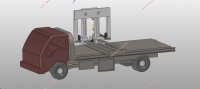
БОЮФдЫгУШ§ЮЌНЈФЃШэМўSolidWorksЃЌЪзЯШеыЖдЧсаЭВрЮЛЕРТЗЧхеЯГЕНјааСЫЗНАИЬНЬжЃЌНјЖјНјааећГЕНЈФЃЃЛЭЌЪБВщдФСЫЯрЙизЪСЯЃЌЖдДЫРраЭЧхеЯГЕЕФзмЬхВМжУНјааЩшМЦЃЌЫљЕУНсЙћЖдгкЧхеЯГЕЮДРДЕФЗЂеЙЗНЯђОпгаживЊЕФжИЕМвтвхЁЃ
ТлЮФжївЊЖдетжжаТаЭГЕСОНјааСЫНсЙЙЗНАИЕФЩшМЦКЭзмЬхВМжУЕФЙцЛЎЁЃ
баОПНсЙћБэУїЃКЧхеЯГЕДгВрУцНјааЧхеЯОпгаРэТлЕФПЩааадЃЌЛљгкЫќЯрБШвЛАуЕФЕРТЗЧхеЯГЕЖјбдИќМгЗНБуЃЌЖдГЁЕивЊЧѓвВМѕаЁЃЌЫљвдЩшМЦетбљвЛжжЧхеЯГЕОпгаживЊЕФбаОПвтвхЁЃ
БОЮФЕФЬиЩЋЃКБОЮФЩшМЦЕФЧхеЯжДааЛњЙЙОпгавЛЖЈЕФДДаТадЃЌзмЬхВМжУгыЩшМЦвВОпгаСМКУЕФПЩВйзїадЁЃ
ЙиМќДЪЃКВрЮЛЧхеЯГЕЃЛНсЙЙЗНАИЃЛЕзХЬбЁаЭЃЛ
Abstract
This article takes advantage of the 3D modeling software SolidWorks. First of all, the article discusses the scheme of the light side road wrecker, and then carries on the vehicle modelling, and consults the related materials to design the overall layout of this type of wrecker. The results obtained have important guiding significance for the future development direction of the wrecker.
The dissertation mainly focuses on the design of the structural scheme and the overall layout of the new vehicle.
The results of the study show that the wrecker has theoretical feasibility for removing obstacles from the side. Because it is more convenient than the ordinary road wrecker, and the site requirements are also reduced, so designing it has important research significance.
The characteristics of this article: The design of the obstacle clearing implement has a certain degree of innovation, and the overall layout and design are maneuverable.
Key WordsЃКSide Wrecker; structure design; chassis selection
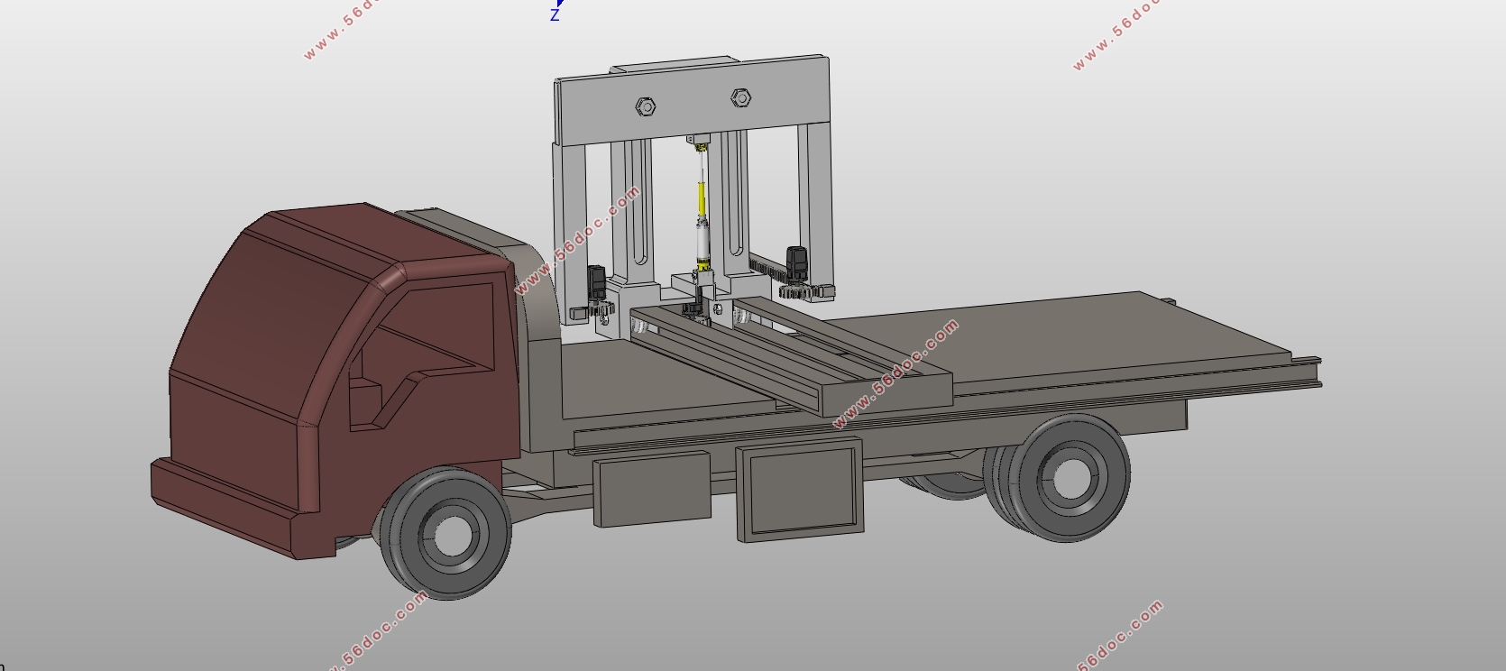
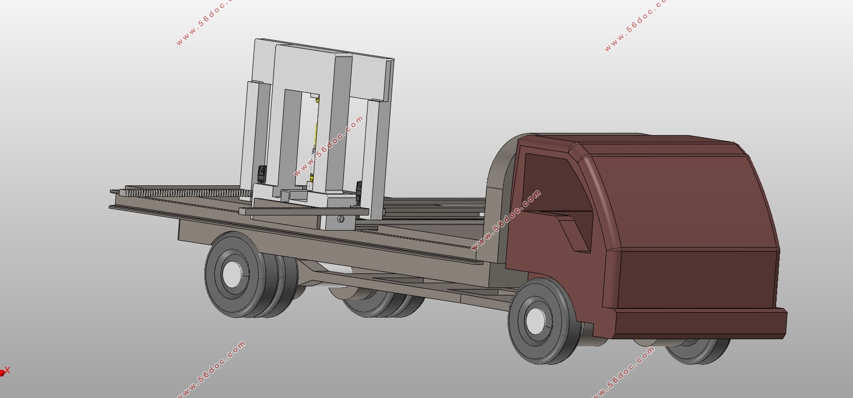
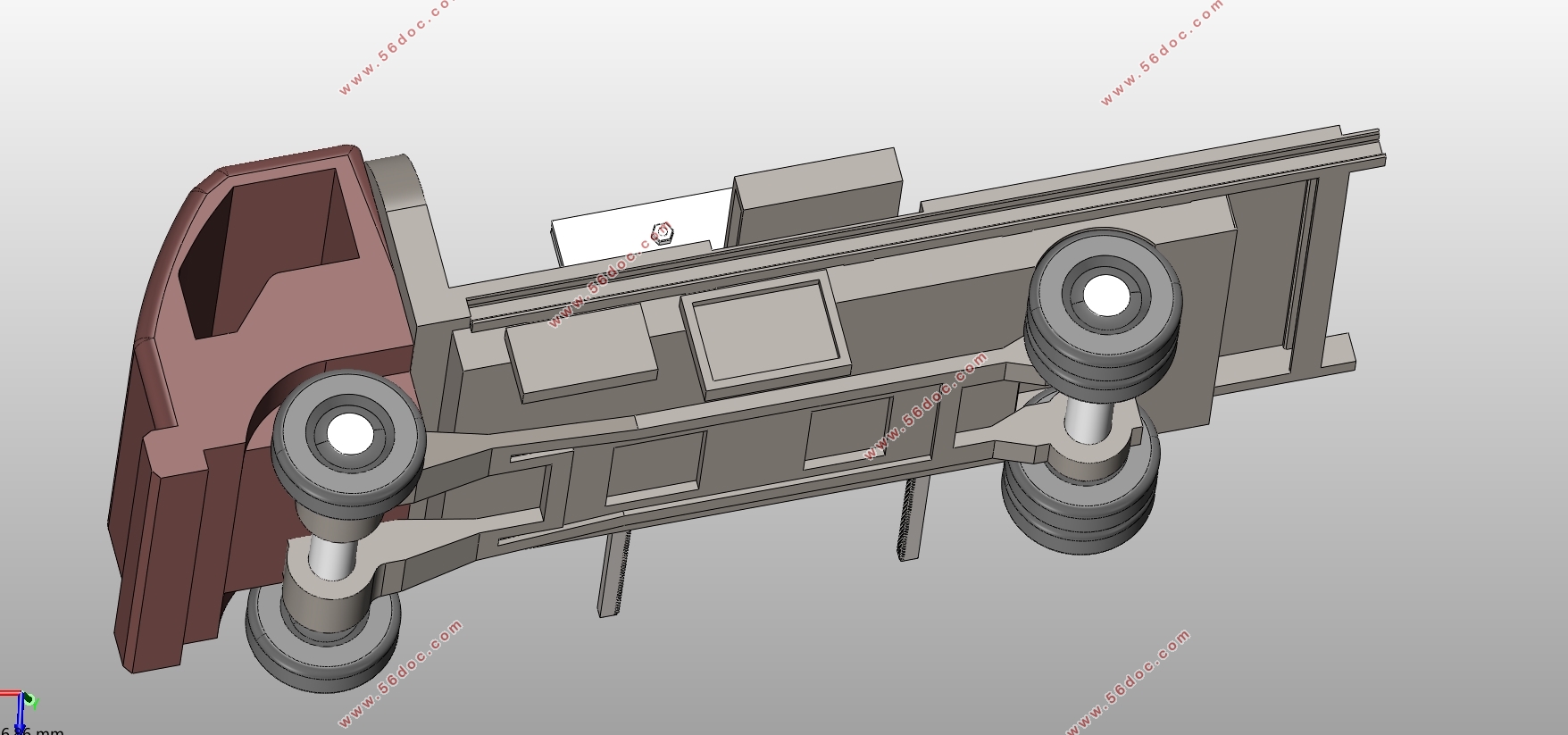
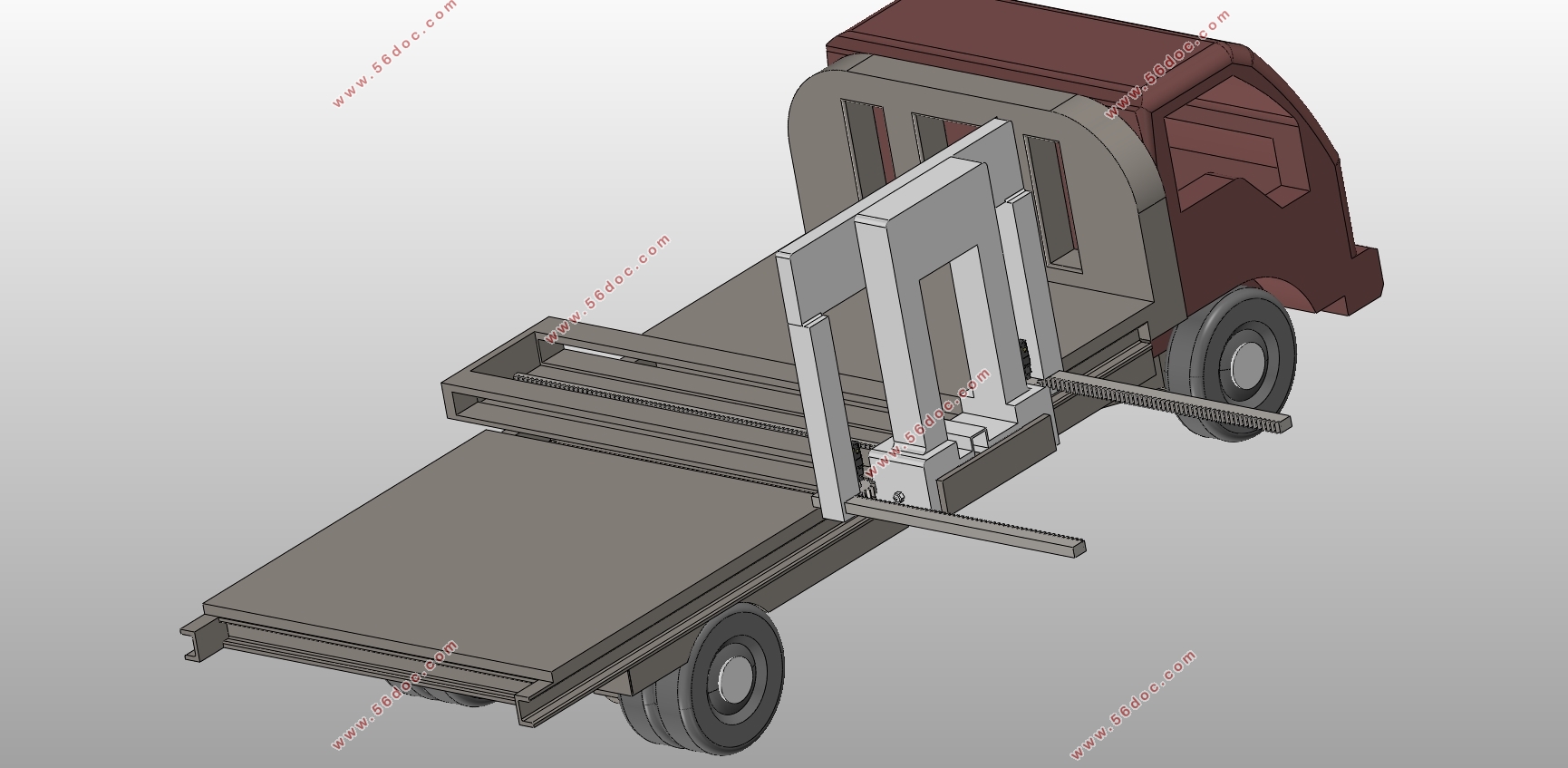
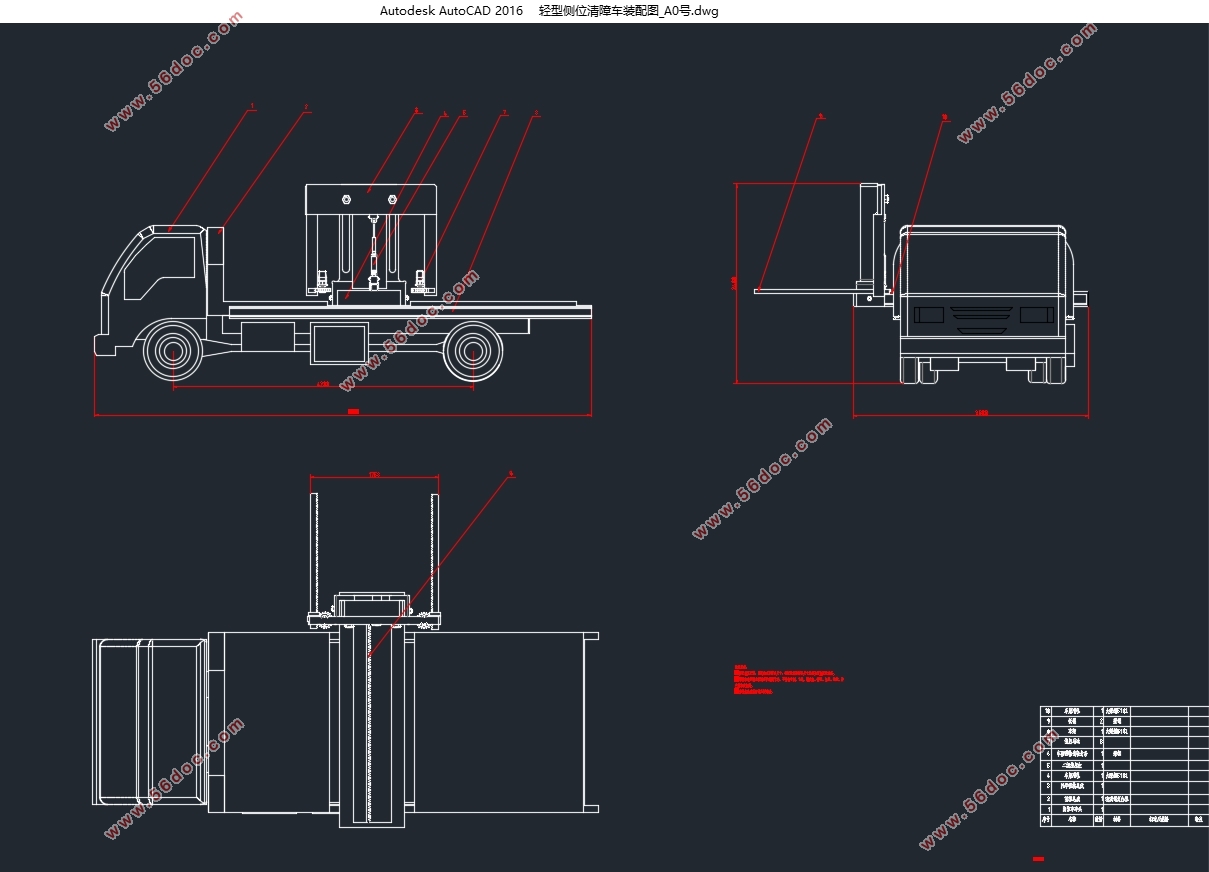
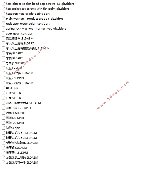
Table of Contents
Chapter 1 Introduction 1
1.1 Research Background 1
1.2 The aim and meaning of the research 4
Chapter 2 Introduction 5
2.1 Argumentation of the Structural Plan 5
2.1.1 Chassis load quality utilization factor 5
2.1.2 The weight of the special equipment 5
2.2 Select structural scheme 6
2.2.1 Horizontal slide structure scheme 6
2.2.2 Vertical lifting mechanism structure scheme 7
2.2.3 Support arm structure scheme 7
2.2.4 Overall structure plan 8
2.3 Determination of hydraulic control 9
Chapter 3 Wrecker Chassis Selection and Design 11
3.1 The determination of the quality parameters of the wrecker 11
3.1.1 Maintenance quality 11
3.1.2 Total mass 11
3.2 The selection of wrecker engine parameter 11
3.2.1 Maximum engine power and its corresponding speed 11
3.2.2 Maximum engine torque and its corresponding speed 12
3.2.3 Engine adaptability coefficientφ 12
3.3 Related parameters of the chassis 13
3.4 Related calculations of the chassis 14
3.4.1 Conditioning mass and axle load distribution 14
3.4.2 Performance parameters 14
3.4.3 Size parameters 15
Chapter 4 The design of Power take-off 17
4.1 The principle and requirement of power take-off 17
4.2 The selection of power take-off 18
Chapter 5 The design of hydraulic system 22
5.1 The introduction and principle of hydraulic system 22
5.2 Hydraulic cylinder structure design 24
5.3 Hydraulic pump device 25
5.3.1 Hydraulic pump installation 25
5.3.2 The connection of hydraulic pump and motor 26
Chapter 6 Design and calculation of actuator 28
Chapter 7 Conclusion 31
References 32
Express thanks 33
|