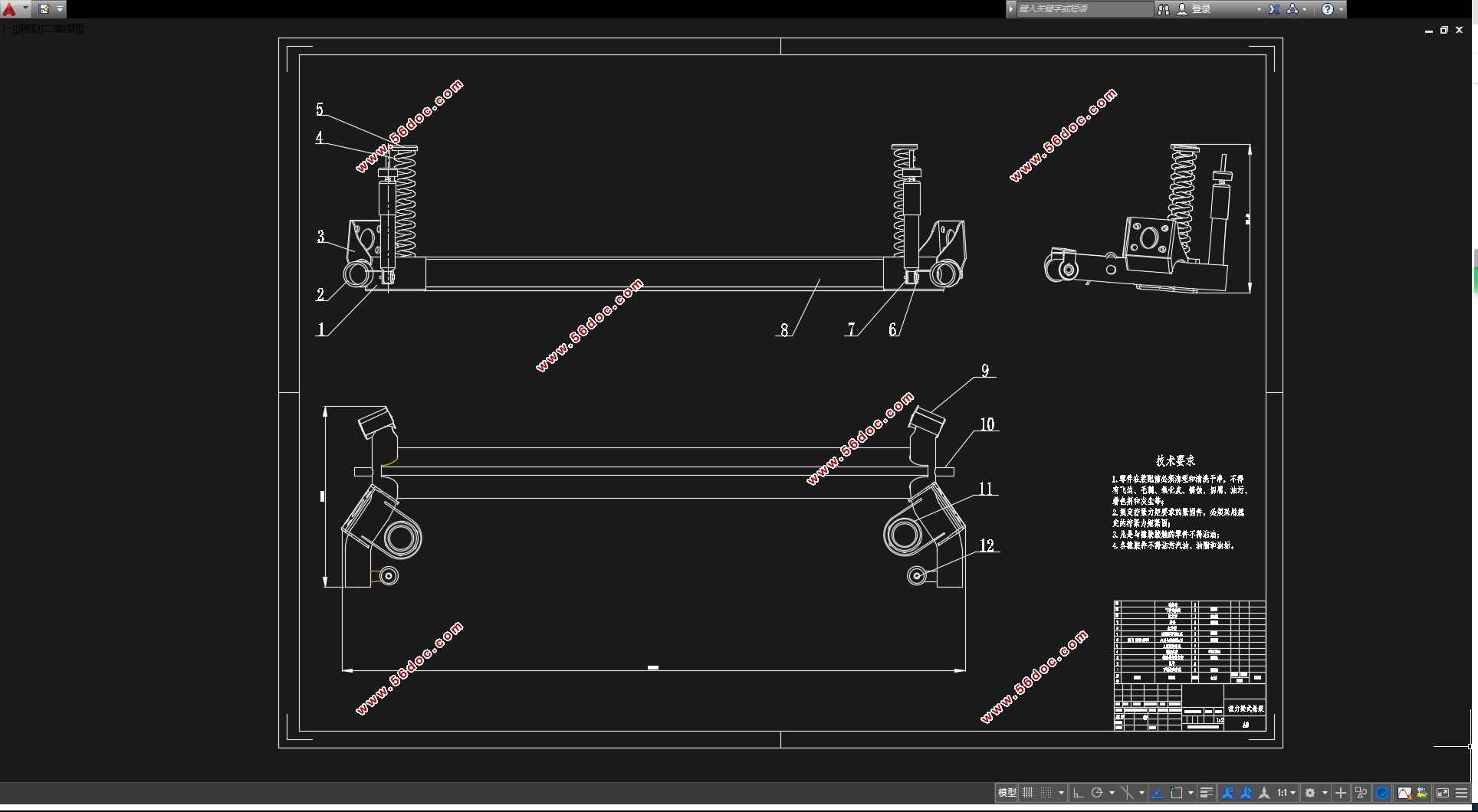
东风风神A60扭力梁后悬架设计(含CAD零件装配图,CATIA三维图)(任务书,开题报告,文献摘要,外文翻译,论文说明书11000字,CAD图8张,CATIA三维图)
摘要
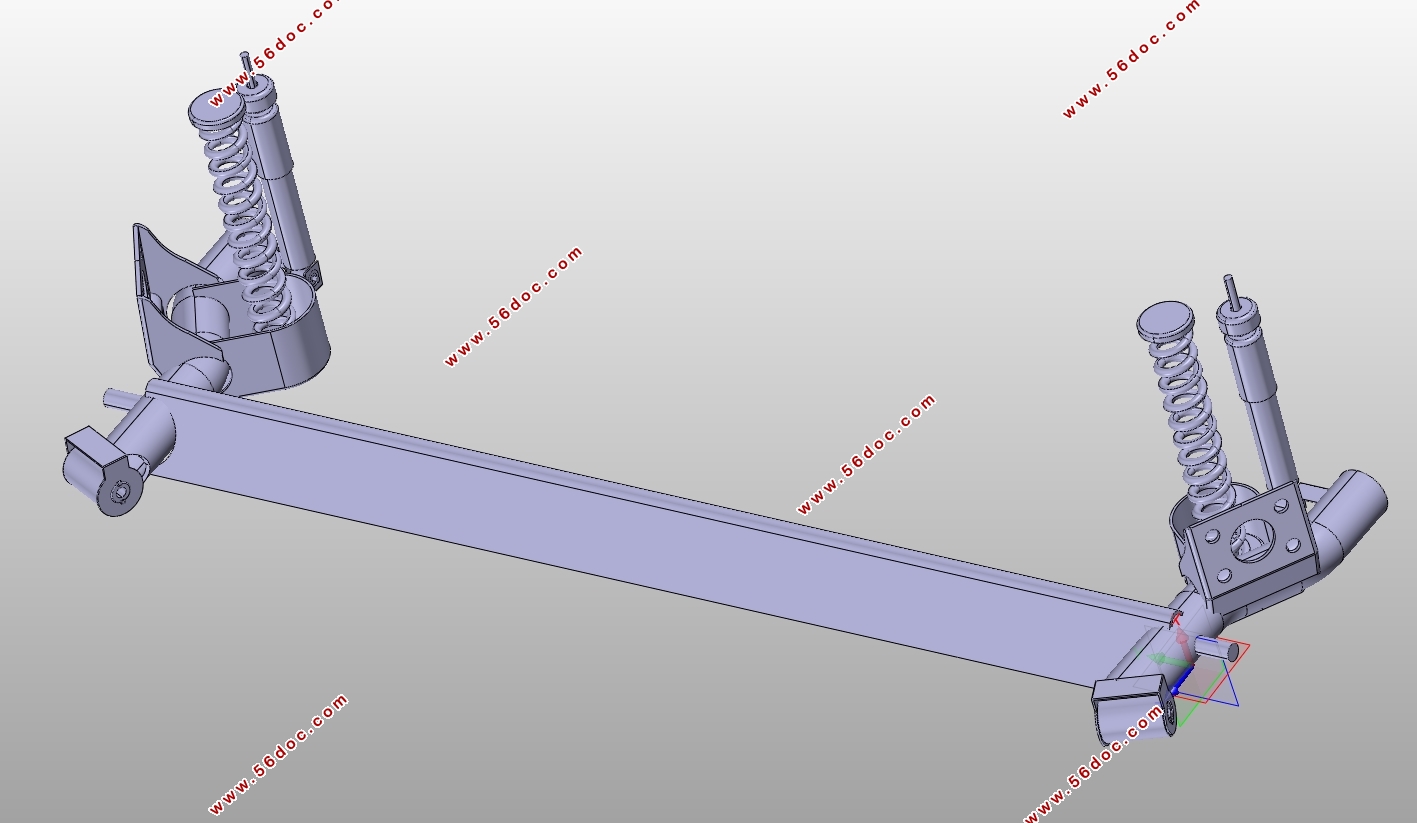
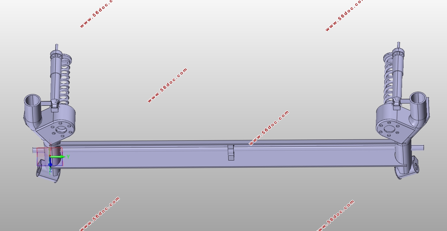
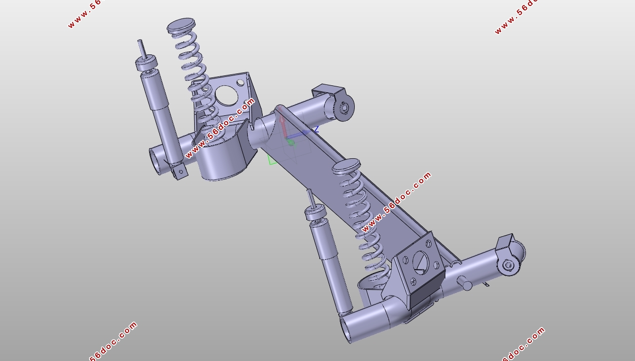
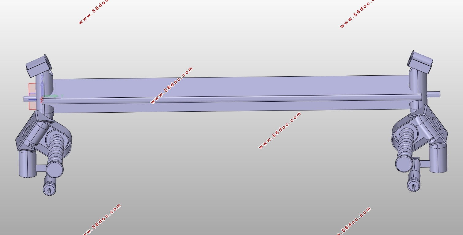
本毕业设计的目的在于依照东风风神A60的悬架性能及舒适性需求,设计出符合行驶要求的后悬架系统。扭力梁式悬架因为低成本、结构简单在紧凑型车型的后悬架而广泛应用,东风风神A60后悬架就采用了单纵臂扭力梁式悬架,它的不同之处在于使用了扭力梁这一构件,进而影响了悬架的整体结构及其他构件的布置形式,因而对扭力梁的总体设计以及其剪切中心的确定、危险截面校核成为本次设计计算过程中的重点。本文在阐明悬架及其构件相应功能的基础上,依照汽车后悬架的设计过程,选取适用本车型的悬架性能参数,对弹性元件、减振器、扭力梁等进行种类选择、计算和设计,并分析可能对悬架性能、减振器性能、扭力梁性能产生影响的各种因素。
关键词:悬架;扭力梁;减振器;螺旋弹簧;单纵臂
Abstract
The purpose of this graduation project is to design a rear suspension system that meets the driving requirements in accordance with the suspension performance and comfort requirements of the Dongfeng Fengshen A60. The torsion beam suspension is widely used in the rear suspension of the compact model because of its low cost and simple structure. The Dongfeng Fengshen A60 rear suspension adopts a single longitudinal arm torsion beam suspension with a stabilizer bar, and its difference is that. The use of a torsion beam component has affected the overall structure of the suspension and the layout of other components. Therefore, the overall design of the torsion beam, as well as the determination of its shear center and the calibration of dangerous sections, have become the key part of this design calculation process. On the basis of elucidating the corresponding functions of the suspension and its components, according to the design process of the rear suspension of the vehicle, the suspension performance parameters applicable to this model are selected, and the elastic components, shock absorbers, torsion beams, etc. are selected and designed, and analyzed. Various factors that may affect the performance of the suspension, damper performance, and torsion beam performance.
Keywords: suspension; torsion beam; shock absorber;spiral spring;single longitudinal arm
东风风神A60性能参数如表4-1。
表4-1 东风风神A60设计数据
东风风神A60相关参数 数据
长宽高/mm 4680*1720*1515
最大功率/kw 85
最大功率转速/rpm 6000
最大扭矩/N•m 145
最大扭矩转速/rpm 4200
整备质量/kg 1208
轴距/mm 2700
后轮距/mm 1540
最小离地间隙/mm 170
目 录
第一章 绪论 - 1 -
1.1课题研究的目的及意义 - 1 -
1.2国内外研究及现状 - 1 -
1.3课题研究内容及预期目标 - 2 -
第二章汽车悬架概述 - 3 -
2.1悬架基本概念 - 3 -
2.2悬架基本组成 - 3 -
2.2.1弹性元件 - 3 -
2.2.2导向机构 - 3 -
2.2.3减振器 - 3 -
2.2.4缓冲块 - 4 -
2.2.5横向稳定器 - 4 -
第三章悬架对汽车性能的影响 - 5 -
3.1悬架对汽车平顺性的影响 - 5 -
3.2悬架对操纵稳定性的影响 - 5 -
3.3悬架弹性特性 - 6 -
第四章悬架主要性能参数的选取 - 7 -
4.1悬架的偏频和静挠度 - 7 -
4.2悬架的动挠度 - 8 -
4.3悬架的工作行程 - 8 -
4.4悬架的刚度 - 8 -
第五章悬架主要构件设计 - 10 -
5.1螺旋弹簧的设计 - 10 -
5.1.1螺旋弹簧类型的选择 - 10 -
5.1.2螺旋弹簧的初步计算 - 10 -
5.1.3螺旋弹簧的刚度 - 11 -
5.1.4螺旋弹簧的其他计算 - 11 -
1. 变形量 - 11 -
2. 高度 - 11 -
3. 节距t - 12 -
4. 螺旋角α - 12 -
5. 展开长度L - 12 -
5.1.5螺旋弹簧的校核 - 12 -
1. 压缩弹簧稳定性验算 - 12 -
2. 压缩弹簧强度验算 - 12 -
3. 共振验算 - 13 -
5.2减振器的设计 - 13 -
5.2.1相对阻尼系数ψ - 14 -
5.2.2减振器阻尼系数δ - 15 -
5.2.3最大卸荷力 - 15 -
5.2.4筒式减振器的工作缸直径D - 16 -
5.2.5减振器的活塞总成设计 - 17 -
1. 活塞杆设计 - 17 -
2. 活塞总成设计 - 18 -
3. 缓冲套设计 - 18 -
4. 导向器及油封设计 - 19 -
5.2.6减振器固定连接形式 - 19 -
5.3扭力梁设计 - 20 -
5.3.1轮胎的静力半径 - 21 -
1.自由半径r - 21 -
2. 静力半径 - 21 -
5.3.2后悬架硬点设计 - 21 -
1. 扭力梁扭转线刚度 - 22 -
2. 其他尺寸的选取 - 23 -
5.3.3扭力梁概念设计 - 24 -
1. 横梁截面 - 24 -
2. 侧倾中心高度 - 25 -
3. 横梁 - 26 -
4. 纵臂 - 26 -
5. 侧倾角刚度 - 27 -
参考文献 - 28 -
致谢 - 29 -
|
