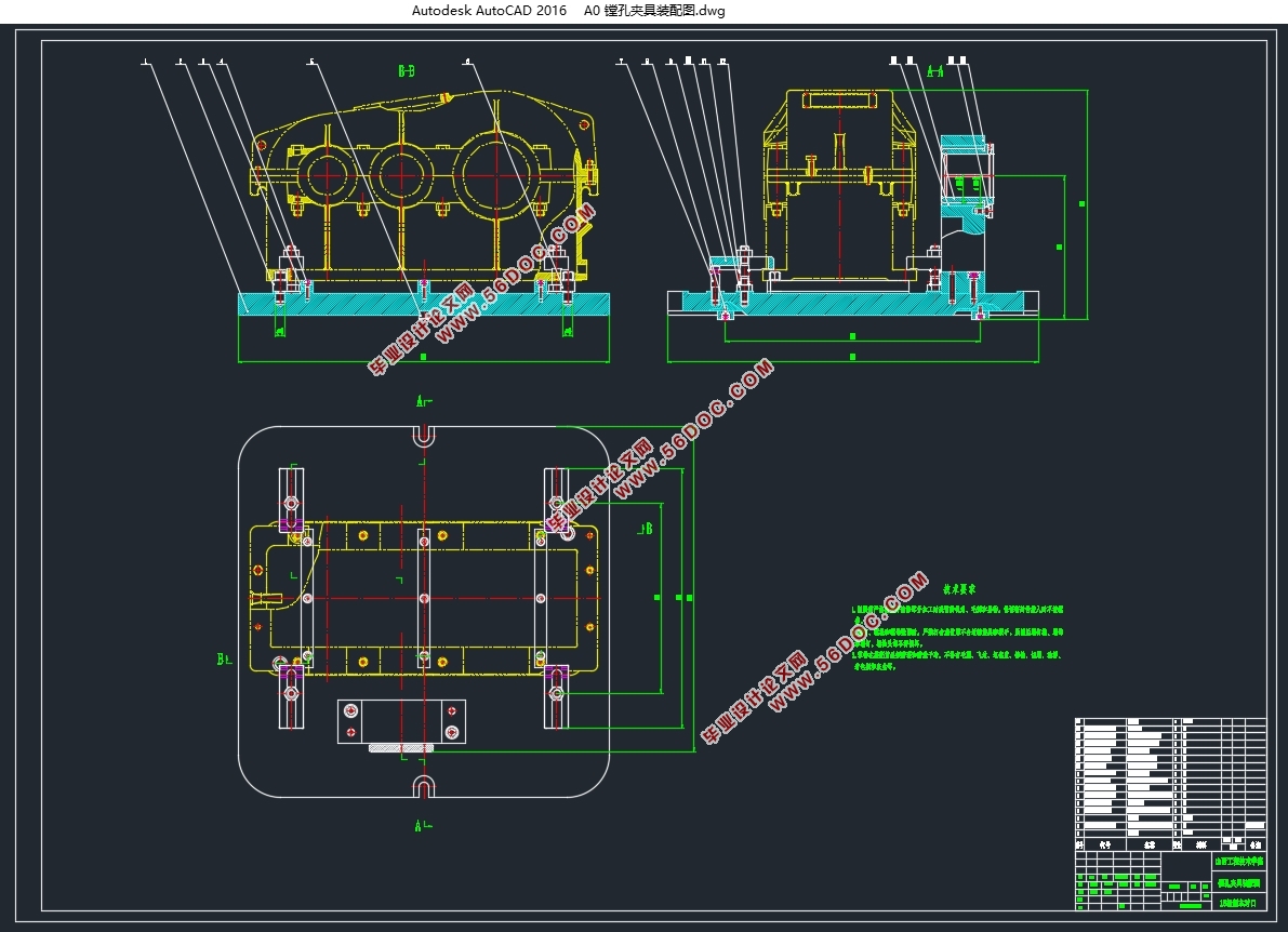
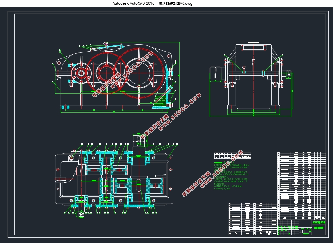
二级圆柱齿轮减速器设计及主要零件加工工艺和夹具设计(含CAD图)(论文说明书21000字,外文翻译,CAD图6张)
摘要
减速器是通过齿轮的速度转换器,将电机的回转数改变为所需要的回转数,并获到较大转矩的一种用来传递动力的机构。在减速器中起着支持和固定轴组件的是减速器箱体,对于保证轴组件运转精度、润滑及密封的可靠都起着重要作用。因此减速器箱体的加工工艺的不断完善对于减速器的使用有着很重要的作用。
本文进行了对减速器箱体的加工工艺和夹具的设计。要对减速器箱体的加工工艺进行细致全面的设计,必须通过制造毛坯采用的形式、选择定位基准、拟定减速器零件加工的工艺路线、通过确定机械生产加工的余量、工序尺寸及制造毛坯的尺寸,以及确定减速器的切削用量及加工的基本工时等方面来设计。通过对减速器箱体加工工艺分析设计,提高减速器箱体制造的加工的工艺的水平,促进减速器箱体制造产业的进步。最后设计镗床专用夹具,分析此夹具的校核以及简要操作说明等等。保证此夹具能在现实当中投入应用进行加工。
关键词:减速器;加工工艺;镗床专用夹具
Design of two - stage cylindrical gear reducer and its main parts processing technology and fixture design
Abstract
Reducer is through the gear speed converter, the number of motor rotation will be changed to the required number of revolutions, and obtain a larger torque used to transfer power of a mechanism. In the reducer, it is the reducer housing that supports and fixes the shaft assembly, which plays an important role in ensuring the running accuracy, lubrication and sealing reliability of the shaft assembly. Therefore, the continuous improvement of the processing technology of the reducer box has a very important role in the use of the reducer.
This article has carried on the reduction gear box processing technology and the fixture design. To the machining process of reducer casing a detailed comprehensive design, must pass through manufacturing adopt the form of the blank, choose the locating datum, proposed reducer parts processing craft route, through the determination of mechanical production and processing of allowance, the size of the process and manufacture the dimensions of the blank, and to determine the speed reducer and the processing of cutting parameter to design the basic working hours, etc. Through the analysis and design of the processing technology of the gearbox, the processing technology level of the gearbox manufacturing is improved, and the progress of the gearbox manufacturing industry is promoted. Finally, the design of special jig boring machine, analysis of the jig check and brief operating instructions and so on. Ensure that this fixture can be used in the real world for processing.
Keywords:reducer;processing technology;special jig boring machine
2.1 设计内容
展开式二级斜齿圆柱减速器,拉力F=4800N,速度v=1.75m/s,直径D=500mm,每天工作小时数:16小时,工作年限(寿命):8年,每年工作天数:300天,配备有三相交流电源,电压380/220V。
3 传动装置总体设计方案
3.1 传动方案
传动方案已给定,减速器为展开式二级圆柱齿轮减速器。
3.2 该方案的优缺点
展开式二级圆柱齿轮减速器由于齿轮相对轴承为不对称布置,因而沿齿向载荷分布不均,要求轴有较大刚度。
带式运输机传动装置的设计
设计条件:
运输带工作拉力F = 4800N;
运输带工作速度v = 1.75m/s;
卷筒直径D = 500mm;
工作条件:两班制,连续单向运转,载荷较平稳,室内工作,有粉尘,环境最高温度35ºC;
使用折旧期:8年;
检修间隔期:四年一次大修,两年一次中修,半年一次小修;
动力来源:电力,三相交流,电压380/220V;
运输带速度允许误差:5%;
制造条件及生产批量:一般机械厂制造,小批量生产。


目 录
摘要 i
Abstract ii
1 概述 1
1.1 设计的目的和意义 1
1.2 国内外研究动态 1
2 减速器设计 3
2.1 设计内容 3
2.2 设计步骤 3
3 传动装置总体设计方案 4
3.1 传动方案 4
3.2 该方案的优缺点 4
4 选择电动机 5
4.1 电动机类型的选择 5
4.2 确定传动装置的效率 5
4.3 选择电动机容量 5
4.4 确定传动装置的总传动比和分配传动比 6
4.4.1 总传动比的计算 6
4.4.2 分配传动装置传动比 6
5 计算传动装置运动学和动力学参数 7
5.1 电动机输出参数 7
5.2 高速轴的参数 7
5.3 中间轴的参数 7
5.4 低速轴的参数 7
5.5 工作机的参数 7
6 减速器高速级齿轮传动设计计算 9
6.1 选定齿轮类型、精度等级、材料及齿数 9
6.2 按齿面接触疲劳强度设计 9
6.2.1 计算小齿轮分度圆直径 9
6.2.2 确定公式中的各参数值 9
6.2.3 试算小齿轮分度圆直径 11
6.3 调整小齿轮分度圆直径 11
6.3.1 计算实际载荷系数前的数据准备 11
6.3.2 计算实际载荷系数KH 11
6.4 确定传动尺寸 12
6.4.1 计算中心距 12
6.4.2 按圆整后的中心距修正螺旋角 12
6.4.3 计算小、大齿轮的分度圆直径 12
6.4.4 计算齿宽 12
6.5 校核齿根弯曲疲劳强度 12
6.6 计算齿轮传动其它几何尺寸 14
6.6.1 计算齿顶高、齿根高和全齿高 14
6.6.2 计算小、大齿轮的齿顶圆直径 15
6.6.3 计算小、大齿轮的齿根圆直径 15
7 减速器低速齿轮传动设计计算 16
7.1 选定齿轮类型、精度等级、材料及齿数 16
7.2 按齿面接触疲劳强度设计 16
7.2.1 小齿轮分度圆直径 16
7.2.2 调整小齿轮分度圆直径 18
7.3 确定传动尺寸 19
7.3.1 计算中心距 19
7.3.2 按照圆整后的中心距修正螺旋角 19
7.3.3 计算小、大齿轮的分度圆直径 19
7.3.4 计算齿宽 19
7.4 校核齿根弯曲疲劳强度 19
7.5 计算齿轮传动其它几何尺寸 21
7.5.1 计算齿顶高、齿根高和全齿高 21
7.5.2 计算小、大齿轮的齿顶圆直径 22
7.5.3 计算小、大齿轮的齿根圆直径 22
8 轴的设计 23
8.1 高速轴的设计计算 23
8.1.1 确定的运动学和动力学参数 23
8.1.2 轴的材料选择并确定许用弯曲应力 23
8.1.3 按扭转强度概略计算轴的最小直径 23
8.1.4 轴的受力分析 24
8.1.5 校核轴的强度 27
8.2 中间轴设计计算 28
8.2.1 确定的运动学和动力学参数 28
8.2.2 轴的材料选择并确定许用弯曲应力 28
8.2.3 按扭转强度概略计算轴的最小直径 28
8.2.4 轴的受力分析 29
8.2.5 校核轴的强度 32
8.3 低速轴设计计算 32
8.3.1 确定的运动学和动力学参数 32
8.3.2 轴的材料选择并确定许用弯曲应力 32
8.3.3 按扭转强度概略计算轴的最小直径 32
8.3.4 轴的受力分析 34
8.3.5 校核轴的强度 36
9 滚动轴承寿命校核 37
9.1 高速轴上的轴承校核 37
9.2 中间轴上的轴承校核 38
9.3 低速轴上的轴承校核 39
10 键联接设计 40
11 减速器的密封与润滑 41
12 减速器箱体主要结构尺寸 42
13 零件图样分析 43
13.1 零件的作用及技术要求 43
13.2 零件结构工艺性分析 43
13.3 毛坯的类型和制造方法 44
14 箱盖工艺规程设计 45
14.1 选择定位基准 45
14.2 拟定加工工艺路线 45
14.3 加工工艺装备的选择 48
14.4 切削用量和基本工时 49
15 镗床专用夹具设计 65
15.1 问题的提出 65
15.2 定位方案设计 65
15.3 夹紧方案设计 65
15.4 主要零部件设计 67
15.5 夹具简要操作说明 67
总结 68
参考文献 69
外文资料 70
中文译文 76
致谢 81
|


