蜗轮蜗杆减速器壳体加工工艺及夹具设计(含CAD夹具图装配图)(论文说明书20000字,外文翻译,CAD图5张)
摘 要
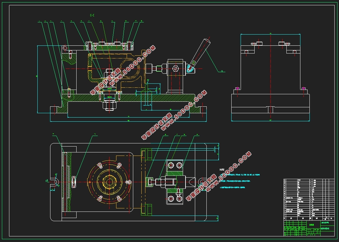
机械工业是一种基本工业形式,对于我们国家来说,它关系到国计民生的方方面面。近年来机械工业领域向着高精度、高质量、高效率、低成本方向发展,数字化,自动化水平日益提高。同时由于机械工业的发展,其他各工业部门也向着高深度迈进,机械工业的发展日趋重要。本设计专用夹具的设计是在蜗轮蜗杆减速器壳体零件加工过程的基础上,主要加工平面和孔。在一般情况下,确保精密加工面比确保精密加工孔要容易。因此,设计遵循的原则是先加工面后加工孔表面。孔加工平面分明显的阶段性,保证粗加工和精加工的加工精度加工孔。通过底面作一个良好的基础过程的基础。主要的流程安排是支持在定位孔过程第一个,然后进行平面和孔定位技术支持上加工孔。整个过程是一个组合的选择工具以及专用夹具夹具的选择,因此,对于大批量,更高的生产力,满足设计要求。
关键词 :蜗轮蜗杆减速器壳体零件;工艺;夹具;
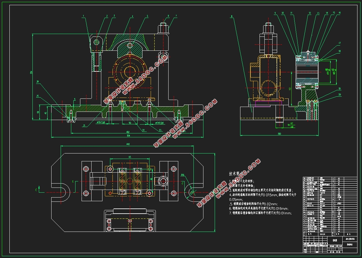
Machining process and fixture design of worm gear reducer shell
ABSTRACT
Machinery industry is a basic industrial form, for ournation speaking, it relates to all aspects of people'slivelihood. Mechanical industries in recent years towardshigh precision, high quality, high efficiency and low costdirection, digital, automation level is increasing day by day.And because the machinery industry development, othervarious industry departments to high depth developmentof forward, the mechanical industry are becoming moreand more important.Foundation design of body parts processing process the design of special fixture. The main processing parts processing plane and holes. In general, ensure easy to guarantee precision machining holes than. Therefore, the design principle is first machined surface after machining hole surface. Periodic hole machining plane is obvious that rough machining and machining precision machining hole. A good foundation on the bottom surface of the process. The main process is supported in the positioning hole process first, and then the processing hole plane and the hole positioning technology support. The whole process is a combination of the selection tool. Special fixture fixture selection, a self-locking mechanism, therefore, for large quantities, higher productivity, meet the design requirements.
Keywords: boxtype parts; technology; fixture;
2 加工工艺规程设计
2.1 零件的分析
2.1.1 零件的作用
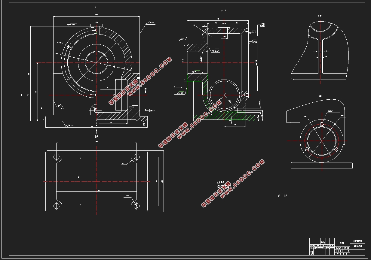
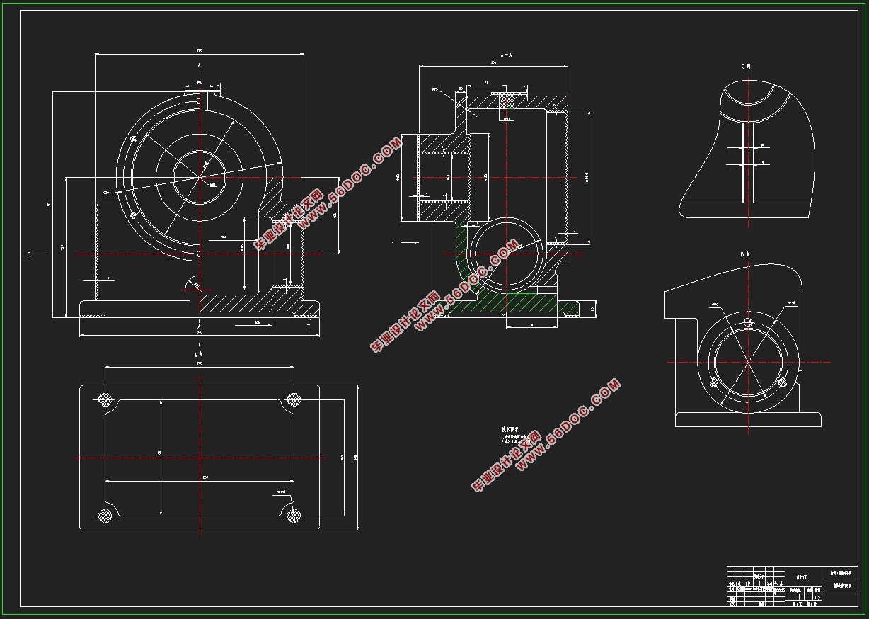
题目给出的零件是蜗轮蜗杆减速器壳体,蜗轮蜗杆减速器壳体零件的加工质量,蜗轮蜗杆减速器壳体零件的加工质量,并确保组件正确安装。
2.1.2 零件的工艺分析
蜗轮蜗杆减速器壳体类零件图。蜗轮蜗杆减速器壳体是一个壳体零件,别安装在五个平面的外表面加工的需要。支持前和后孔。此外,表面还需加工一系列孔。可分三组加工表面。分析如下:
(1)以底平面加工面。这一组加工表面包括:底面铣削加工;4-Φ18mm孔。
(2)以185-70孔的支承孔为加工面。这一组包括:185-70镗孔。
(3)以Φ40凸台面为加工面。这一组加工表面包括:Φ40凸台面铣削加工;M20螺纹孔
(4)以φ230大端面为加工面
主要加工表面有以下5个主要加工表面;
1.端面 通过粗铣精铣达到1.6精度要求
2.内圆 粗镗、半粗镗、精镗达到6.3的精度要求
3.内表面 先粗铣后精铣的3.2的精度要求
4.底面 通过粗铣直接使底面精度达到12.5
5. 凸台端面 在凸台端面使其达到12.5的精度要求

目 录
摘 要 i
Abstract ii
1 引 言 1
1.1 国外研究动态: 1
1.2 国内研究现状 1
1.3 本课题研究的内容和意义 2
1.4 机械加工工艺概述 2
1.5 机械加工工艺流程 3
1.6 夹具概述 3
1.7 机床夹具的功能 4
1.8 机床夹具的发展趋势 4
1.8.1 机床夹具的现状 4
1.8.2 现代机床夹具的发展方向 5
2 加工工艺规程设计 6
2.1 零件的分析 6
2.1.1 零件的作用 6
2.1.2 零件的工艺分析 6
2.2 蜗轮蜗杆减速器壳体加工措施 6
2.2.1 孔和平面的加工顺序 7
2.2.2 孔系加工方案选择 7
3 蜗轮蜗杆减速器壳体加工定位基准的选择 8
3.1 粗基准的选择 8
3.2 精基准的选择 8
3.3 蜗轮蜗杆减速器壳体加工主要工序安排 9
3.4 机械加工余量、工序及毛坯的确定 12
3.5 确定切削用量及基本工时(机动时间) 12
4 镗185-70孔夹具设计 30
4.1 研究原始质料 30
4.2 定位、夹紧方案的选择 30
4.3 切削力及夹紧力的计算 30
4.4 误差分析与计算 31
4.5 定位销选用 32
4.6 夹具设计及操作的简要说明 32
5 钻6-M8底孔的钻床夹具设计 33
5.1 夹具的夹紧装置和定位装置 33
5.2 夹具的导向 34
5.3 切削力及夹紧力的计算 34
5.4 钻孔与工件之间的切屑间隙 37
5.5 钻模板 38
5.6 定位误差的分析 38
5.7 钻套、衬套、钻模板设计与选用 39
5.8 确定夹具体结构和总体结构 41
5.9 夹具设计及操作的简要说明 42
结束语 43
参 考 文 献 44
附 录: 45
外文资料 52
中文译文 57
致 谢 61
|
