发动机连杆加工工艺及夹具设计(附CAD零件图夹具图总成图)(论文说明书23000字,CAD图7张)
摘 要
柴油机的主要运动件由活塞、连杆组件和曲轴组成,连杆是它的重要传动件之一。[13]随着汽车工业制造技术的飞速发展,人们对汽车发动机的动力性和可靠性越来越重视,而连杆的强度、刚度对提高这两个因素至关重要,所以发动机连杆的设计和加工值得我们重视。[5]
柴油机工作时,压缩冲程把燃油和空气的混合物压缩,使温度升高达到其燃点从而点火燃烧在气缸中产生热能,使活塞顶面产生膨胀的压力,此压力由连杆传递给曲轴,在此同时,连杆本身又受曲轴的来回推动带动活塞压缩气缸中的气体。[15]连杆在工作过程中承受着剧烈变化的动载荷。连杆分为两部分,连杆体和连杆盖。连杆体和连杆盖上的大头孔通过螺栓和螺母与曲轴联接在一起。[14]
本文对连杆的加工工艺及夹具设计进行了详细阐述。在设计过程中,我们以路虎神行者2TD4柴油机为例设计连杆。由于柴油机压缩比较高,对连杆的强度要求也会高。我们面临着连杆刚性比较差容易产生变形这个现实问题,然而连杆的尺寸精度、形状精度和位置精度的要求又都很高,因此在工艺过程的安排中,就应该对主要表面的粗精加工工序进行分类,来逐渐减少加工余量、切削力和内应力的作用,并对加工后产生的变形进行修正,最终达到零件的技术要求。
关键词:连杆 夹具设计 加工余量 加工工艺 精度
The engine connecting rod processing technology and fixture design
Abstract
The main moving parts of the diesel engine are made up of the piston,connecting rod components and the bent axle.The connecting rod is one of the main transmission parts of diesel engine.[13]With the rapid development of auto industry manufacture technology,we pay more attention on the power performance and reliability of automobile engine.However,the strength and stiffness of the connecting rod are very important to improve the two factors.So,the design and processing of the connecting rod are worth our attention.[5]
When the diesel engine works,the compression stroke takes a mixture of fuel and air compression.It makes the temperature higher,and reaches its flash point,and burns in the cylinder to produce heat.The top surface of piston brings the expansion of the pressure which is passed to the crankshaft by the connecting rod.At the same time,the connecting rod itself drives the piston to cut down the gas in cylinder.[15]Connecting rod is under dynamic load of a sharp change in work.Connecting rod is made up of two parts,connecting rod body and cover.The big hole of connecting rod body and connecting rod cover is together with the crankshaft by bolts and nuts.[14]
The main transmission link is one of a diesel engine,the paper mainly discusses the process and connecting fixture design.In the process of design,we take the land rover free lander 2 TD4 diesel engine as an example. The connecting the dimension precision,accuracy and precision of the shape of requirements are very high,but the connecting rod of rigid,easily,so in the arrangement of deformation process,the major surface coarse finishing processes.Gradually reduce limits,but cutting force and effect of stress,and the deformation after processing,can finally reached the technical requirements of the parts.
Keywords: connecting rod;fixture design;Machining allowance;The processing technology;precision
1.涉及的具体内容有:
(a)发动机连杆的主要技术要求,材料选择等;
(b)连杆的加工工艺过程分析;
(c)定位基准的选择和切削量的计算;
(d)计算工艺尺寸链;
(e)主要夹具的三维模型设计
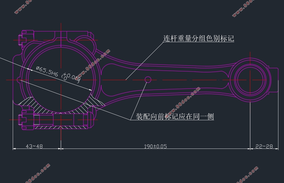
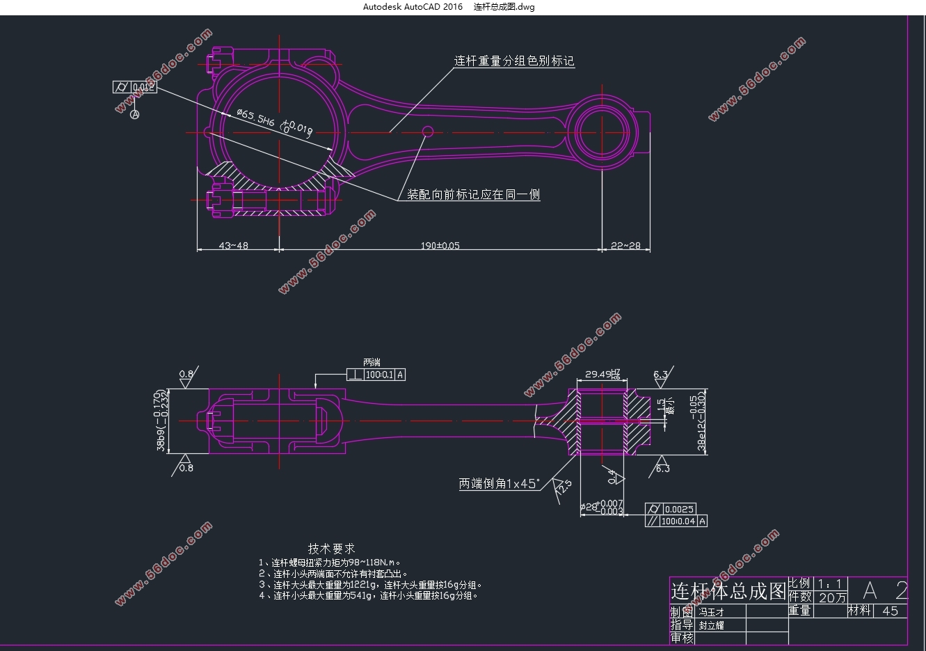
2.本次设计要求达到的连杆尺寸及公差如下:
(a)大小孔中心距:190±0.05mm
(b)大头孔公差等级IT6,表面粗糙度Ra不大于0.4μm,大头孔圆柱度公差0.012mm,小头孔公差等级IT8,表面粗糙度小于3.2μm。
(c)结合面公差0.025mm
(d)产量:大量生产,模锻制造毛坯

目 录
摘 要 I
Abstract II
第一章 绪论 1
1.1 课题的目的及意义 1
1.2 发动机连杆的国内外现状 1
1.3 任务书 3
第二章 连杆的工艺分析 5
2.1 连杆的结构特点 5
2.2 连杆的技术要求 6
2.2.1大、小头孔的尺寸精度和形状精度 7
2.2.2 大、小头孔轴心线在两个互相垂直方向的平行度 7
2.2.3 大、小头孔中心距 8
2.2.4 连杆大头孔两端面对大头孔中心线的垂直度 8
2.2.5 大小头孔两端面的技术要求 8
2.2.6 螺栓孔的技术要求 8
2.2.7 有关结合面的技术要求 8
第三章 工艺规程设计 9
3.1 连杆的材料和毛坯 9
3.2 连杆的结构工艺性分析 10
3.3 基面的选择 11
3.3.1 粗基准的选择 12
3.3.2 精基准的选择 12
3.4 连杆合理的夹紧方法 13
3.5 夹具使用 13
3.6 连杆主要表面的加工方法 14
3.7 制定工艺路线 16
3.8 确定机械加工余量 18
3.9 确定工序尺寸及其公差 19
3.10 计算工艺尺寸链 19
3.11 确定切削用量及基本工时 21
3.11.1 切削用量的确定 21
3.11.2 工时定额的计算 22
3.12 连杆的检验 40
3.12.1 观察外表缺陷及目测表面粗糙度 40
3.12.2 连杆大头孔圆柱度的检验 40
3.12.3 连杆螺钉孔与结合面垂直度的检验 40
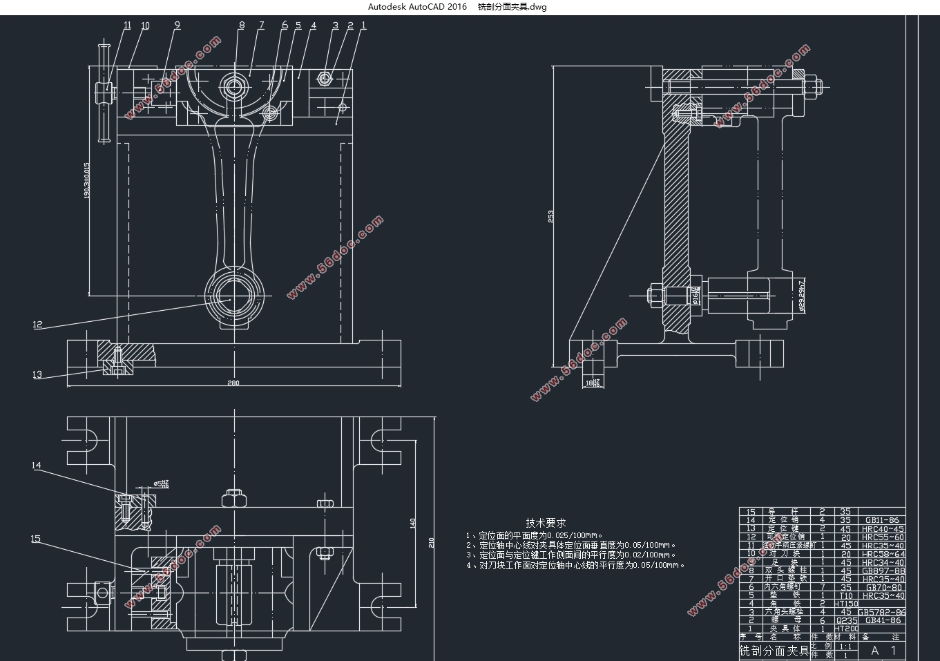
第四章 夹具设计 41
4.1剖铣分面夹具设计 41
4.1.1问题的指出 41
4.1.2 夹具设计 41
4.2 扩大头孔夹具 43
4.2.1问题的指出 44
4.2.2 夹具设计 44
参考文献 48
致谢 49
|