柴油机气缸体顶底面粗铣夹具设计(选题审批表,任务书,开题报告,过程检查表,毕业论文10000字,cad图纸5张)
摘要:
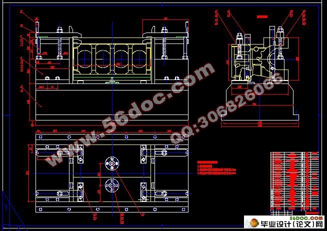
本设计课题为柴油机气缸体顶底面粗铣夹具设计,拟订夹具的结构方案、绘制夹具总图及其零件图。
根据气缸体尺寸、形状、材料、加工部位的结构和加工精度、表面粗糙度等要求,确定选用卧式双面铣组合机床;为实现工件快进和工进配以移动工作台;被加工平面为大平面,材料为HT250,故刀具选择硬质合金端铣刀。夹具安装在移动工作台之上。在被加工零件的定位方面,本方案采用了“一面两销”的定位方式,以达到较好的定位效果。夹紧是通过手动夹紧,以四个压板实现夹紧,这样能很好的防止夹紧力作用下工件产生形变。由于被加工零件体积、重量较大,故采用支承板支承。另外通过夹具误差设计分析,能够较好地保证加工精度。
通过这样的设计来达到加工要求,以便能完成对柴油机气缸体顶底的粗铣,满足工厂制定的产量。
关键词:组合机床; 夹具; 气缸体; 铣削
Diesel engine cylinder body top and bottom surface rough milling fixture design
This design task for diesel engine cylinder block top underside rough milling fixture design, and formulate fixture structure scheme, draw fixture and general drawing.
According to the cylinder body size, the shape, the material, processing request and so on spot structure and processing precision, surface roughness, determined selects the horizontal-type two-sided mill aggregate machine-tool; In order to realize the work piece to enter quickly with the labor enters matches by moves the work table; Is processed the plane is the big plane, the material is HT250, therefore cutting tool choice hard alloy face cutter. The jig installs in moves above the work table. In is processed the components the localization aspect, this plan has used "two sells at the same time" the locate mode, by achieves the good localization effect. Clamps is through manual clamps, clamps by four clamps realizations, like this can very good prevent clamps under the action of force the work piece to have the deformation. Because is processed the components volume, the weight is big, therefore uses the support plate supporting. Moreover designs the analysis through the jig error, can guarantee the processing precision well.
I complete the design requirements according to such design, so that I can complete to the diesel engine was mad the cylinder body goes against the bottom the thick mill, satisfy the factory formulation the output.
Key words: modular machine-tool; jig; cylinder body ; milling
3机床的选择
3.1被加工零件分析
被加工零件:柴油机气缸体
材料:HT250
硬度:HB180-240
年产量:65000件
加工部位:顶底面
加工要求:气缸体表面粗糙度被加工到6.3 ,顶底面尺寸至427±0.3mm。
3.2机床结构的确定
根据被加工零件加工要求:顶底面两面粗铣,选择双面铣组合机床。
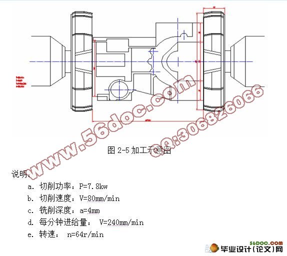
被加工零件置于移动工作台上,两边分别设两把铣刀,以两个电动机驱动。
另外还应有部件包含:两个侧底座,一个中间底座,两个铣削头,及两个主轴箱及夹具。
3.3 本组合机床的特点
a.结构牢固, b.刚性好, c.尺寸调整范围大, d.单位工作效率高, e.精确度好,f.操作简便,g.可对铸件进行大行程走刀,h.强力铣削。
3.4 切削用量的确定
在组合机床工艺方案确定过程中,工艺方法和关键工序的切削用量选择是十分重要。切削用量选择是否合理,对组合机床的加工精度、生产率、刀具耐用度、机床的结构形式及工作可靠性均有较大的影响。
3.4.1切削用量选择的特点
a.组合机床长采用多刀多刃同时切削,为尽量减少换刀时间和刀具的消耗,保证机床的生产率及经济效果,选用的切削用量比普通机床单刀加工时低30%左右。
b.组合机床通常用动力滑台来带动刀具进给。因此,同一滑台带动的多轴箱上所有刀具的每分钟进给两相同,即等于滑台的工进速度。
3.4.2切削用量选择的方法
a.应尽量作到合理使用所有刀具,充分发挥其使用性能。
b.复合刀具切削用量选择应考虑刀具的使用寿命。
c.多轴镗孔主轴刀头均需定向快速进退时,各镗轴转速应相等或成整数倍。
3.5 选择工作台
根据被加工要求,即同时铣气缸体的两面,铣刀在加工过程中不移动,故选择移动工作台。由移动工作台在加工过程中,实现快进和工进。
根据被加工零件尺寸:
被加工平面250×250mm和330×330mm,顶底面距离为427mm,
移动工作台的宽度W=800mm;
铣削宽度:a =580mm,夹具底座宽1140mm,
移动工作台的最小行程为1150mm
目录
1摘要: 1
2前言 3
3机床的选择 4
3.1被加工零件分析 4
3.2机床结构的确定 4
3.3 本组合机床的特点 4
3.4 切削用量的确定 4
3.4.1切削用量选择的特点 4
3.4.2切削用量选择的方法 4
3.5 选择工作台 5
3.6 选择侧底座 5
3.7 选择中间底座 6
3.8 被加工零件工序图 6
3.9 加工示意图 7
4 夹具的设计 7
4.1概述 7
4.1.1夹具的作用 7
4.1.2机床夹具的分类 8
4.1.3机床夹具的组成 8
4.1.4夹具设计方法与步骤 9
4.2设计的前期准备 9
4.3定位装置的确定 9
4.3.1概述 9
4.3.2定位方式 10
4.3.3定位元件 10
4.4确定夹紧方案 12
4.4.1设计夹紧装置的要求 12
4.4.2夹紧力的确定 12
4.5 其它元件的设计 14
4.6夹具的公差配合与技术要求 14
4.6.1制定夹具公差与技术要求的基本原则 14
4.6.2夹具公差的制定 15
4.6.3夹具技术要求的制定 16
4.7工序的精度分析 17
4.7.1定位误差的分析与计算 17
4.7.2夹紧误差的分析与估算 18
4.7.3对刀和导向误差 18
4.7.4夹具的位置误差 18
4.7.5加工方法误差 19
4.7.6保证加工精度的条件 19
5总 结 21
参 考 文 献 22
致 谢 23
附 录 24
附 录
序号 图名 图号 图副
1 加工工序图 YG02-0001 A3
2 加工示意图 YG02-0002 A2
3 夹具总装图 YG02-2001 A0
4 手柄 YG02-2044 A4
5 削边销 YG02-2048 A4
|


