液压控制的移置机械手的设计(含CAD零件图装配图)(选题审批表,任务书,开题报告,中期检查表,论文说明书10800字,CAD图5张)
摘 要:本次设计的液压传动机械手根据规定的动作顺序,综合运用所学的基本理论、基本知识和相关的机械设计专业知识,完成对机械手的设计,并绘制必要装配图、液压系统图。机械手的机械结构采用油缸、螺杆、导向筒等机械器件组成;在液压传动机构中,机械手的夹紧、伸缩、升降、横移均采用伸缩油缸。文章主要叙述了机械手的设计计算过程,全面详尽的讨论了搬运机械手的手部、手臂以及机身等主要部件的结构设计。
本设计的机械手可在空间抓放物体,可代替人工在高温和危险的作业区进行作业,可抓取重量较大的工件。
关键词: 机械手;液压;控制回路
The Design Of Displacement Manipulator Based On Hydrolytic Control
Abstract: The design of hydraulic driving manipulator according to the order of moves, use the basic theory, basic knowledge and related mechanical design expertise comprehensively to complete the design of manipulator, and drawing the necessary assembly, hydraulic system map. Manipulator mechanical structure using tanks, screw, guide tubes and other mechanical device component; In the hydraulic drive bodies, manipulator arm clamping, telescopic, lifting and traverse using telescopic tank. The paper mainly narrated the design and calculation of light and transfer manipulator, The comprehensive exhaustive discussion has transported manipulator's hand, the arm, the fuselage and so on ,which the major structural design computation.
The design of the information on the manipulator can grasp up in space objects ,can replace the artificial heat and dangerous operation conducted operations,and can grasp the larger work pieces .
Keywords : Manipulator ; Hydraulic; Control Loop
目 录
摘要 …………………………………………………………………………………………1
关键词 ………………………………………………………………………………………1
1 绪论 ……………………………………………………………………………………2
1.1 前言 ……………………………………………………………………………2
1.2 工业机械手在生产中的应用 ………………………………………………………………………2
1.3 机械手的组成 …………………………………………………………………3
1.3.1 执行机构 ………………………………………………………………3
1.3.2 驱动机构 ………………………………………………………………4
1.3.3 控制系统分类 …………………………………………………………4
2 总体设计方案 …………………………………………………………………………4
2.1 机械手的确定…………………………………………………………………4
2.2 驱动机构的选择 ………………………………………………………………5
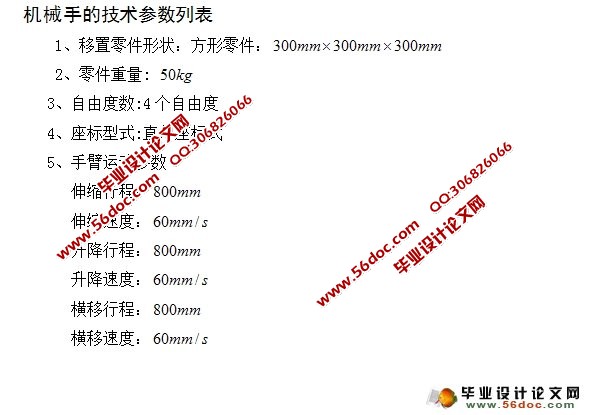
2.3 机械手的技术参数列表 ………………………………………………………5
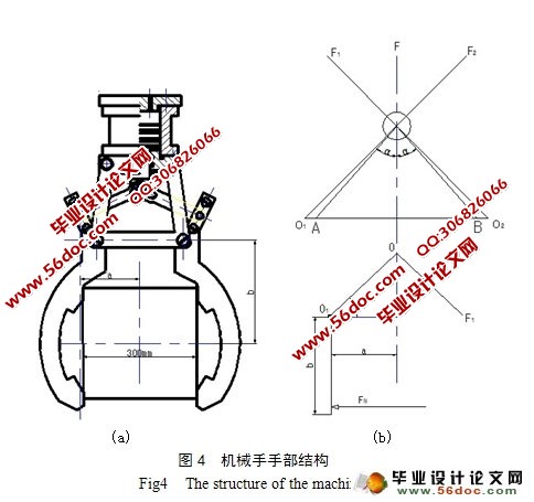
3 机械手手部的计算 ……………………………………………………………………6
3.1 手部设计时应注意的问题 …………………………………………………6
3.2 典型的手部结构 ………………………………………………………………6
3.3 机械手手部结构的设计计算 …………………………………………………6
3.3.1 选择手部的类型及夹紧装置 …………………………………………6
3.3.2 夹紧力及驱动力的计算 ………………………………………………7
3.4 弹簧的设计计算 ………………………………………………………………8
4 机械手的腕部 ………………………………………………………………………10
5 机械手臂部的设计及计算 ……………………………………………………………10
5.1 臂部设计时应注意的问题 ……………………………………………………10
5.2 手臂的典型结构以及结构的选择 ……………………………………………10
5.2.1 手臂的典型运动结构 …………………………………………………10
5.2.2 手臂运动机构的选择 …………………………………………………11
5.3 X方向 …………………………………………………………………………11
5.3.1 手臂摩擦力的分析与计算 ……………………………………………11
5.3.2 手臂惯性力的计算 ……………………………………………………12
5.3.3 液压缸工作压力和结构的确定 ………………………………………13
5.3.4 确定液压缸的尺寸 ……………………………………………………13
6 机身的设计计算 ………………………………………………………………………14
6.1 机身设计时应注意的问题 ……………………………………………………14
6.2 Y方向 …………………………………………………………………………15
6.3 Z方向 …………………………………………………………………………15
7 液压元件的选择 ………………………………………………………………………17
7.1 主要技术参数 …………………………………………………………………17
7.2 液压泵的选择 …………………………………………………………………17
7.3 确定电机功率 …………………………………………………………………18
7.4 液压阀的选择 …………………………………………………………………18
7.5 油管的设计 ……………………………………………………………………19
7.6 油箱的设计 ……………………………………………………………………19
8 液压系统的验算 ………………………………………………………………………20
8.1 压力损失的验算 ………………………………………………………………20
8.1.1 回路压力损失的验算 …………………………………………………20
8.1.2 局部压力损失的验算 …………………………………………………20
8.2 计算液压系统的发热升温 ……………………………………………………21
小结 ………………………………………………………………………………………22
参考文献 …………………………………………………………………………………23
致谢 ………………………………………………………………………………………23
附录 ………………………………………………………………………………………24
附录
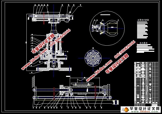
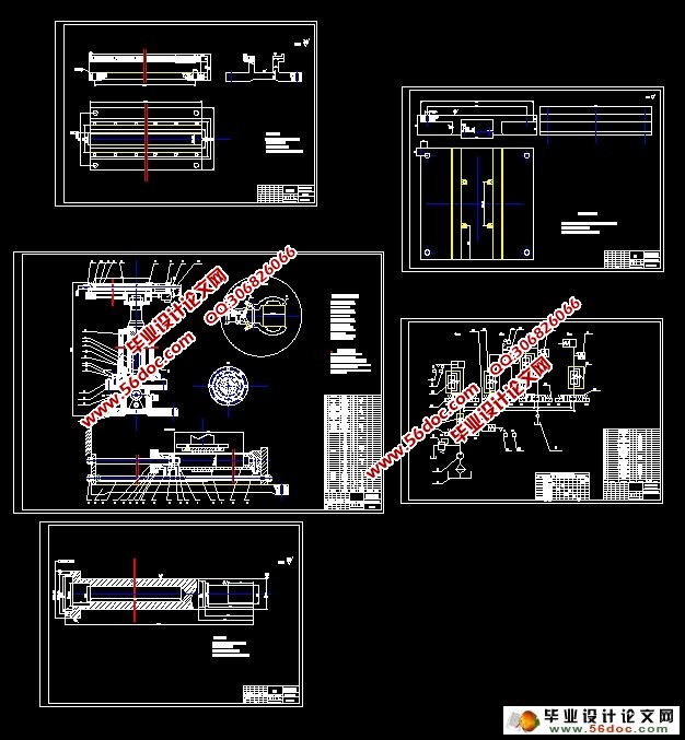
附件1:系统装配图 1张
附件2:液压控制原理图 1张
附件3:零件图 3张
|