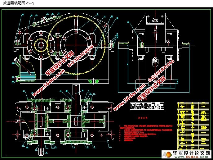
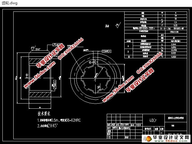
二级圆柱齿轮减速器的设计(含CAD零件装配图)(设计说明书10000字,CAD图纸3张)
摘要
减速器是一种由封闭在刚性壳体内的齿轮传动所组成的独立部件,常用在动力机与工作机之间作为减速的传动装置,在少数场合下也用作增速的传动装置,这时就称为增速器,减速器由于结构紧凑,效率较高,传递运动准确可靠,使用维护简单,并可成批生产,故在现代机械中应用很广。
汽轮机的减速器都采用斜齿轮,斜齿一般具有渐开形,新的减速器齿轮采用螺线形斜齿轮。汽轮机减速器齿轮是将斜齿轮成组的组装在一起成为人字形齿轮组,用来平衡斜齿轮工作时的轴向推力,从而保证齿轮啮合良好。在有些小型汽轮机的减速器上,靠发电机侧的大齿轮轴承,除有支承作用外,在轴承两侧还浇铸有乌金,并开有倾斜油槽,与装在大齿轮轴上的两个推力盘组成推力轴承,来承受轴向推力。大齿轮工作时的轴向推力,可能来自发电机,也可能是斜齿轮工作时残余的轴向不平衡推力。
关键字:齿轮;传动比;减速器。
Abstract
Reducer is a kind of enclosed by a rigid shell gear in the transmission, which is composed of independent components, commonly used as gear between the power machine and work, in a few cases is also used as a speed transmission device, then said speeder, reducer due to compact structure, high efficiency transmission movement, accurate and reliable, simple maintenance and batch production, so in the modern machinery is widely used.
Turbine reducer adopts helical gears, bevel generally has gradually open form, the new reduction gear using spiral bevel gear. The reducer gear of the turbine is assembled together with the helical gear into a human form gear set, which is used to balance the axial thrust of the helical gear in order to ensure the gear meshing well. In some small turbine reducer on, rely on the generator side gear bearing, in addition to a supporting role, on the two sides of the bearing also cast Ugyen, and is provided with an inclined oil groove, and installed in the gear shaft of the two thrust disc composed of thrust bearing, to bear the axial thrust. The axial thrust of the big gear, which may come from the generator, may also be the axial unbalance thrust of the helical gear.
Key words: gear; transmission ratio; gear reducer.
该减速箱用于卷筒输送带,工作速度不高(V=1.5m/s),输送带工作拉力不大(F=1200N),因而传递的功率也不会太大。由于工作运输机工作平稳,转向不变,使用寿命不长(10年),故减速箱应尽量设计成闭式,箱体内用油液润滑,轴承用脂润滑.要尽可能使减速箱外形及体内零部件尺寸小,结构简单紧凑,造价低廉,生产周期短,效率高。
目录
第一章 工作机器特征的分析 1
第二章 传动方案的设计 2
第三章 选择电动机 3
3.1 求电机至工作机之间的传动装置的总效率 3
3.2计算电机所需功率 4
3.3确定电动机的转速 4
3.4电动机的外形和安装尺寸 4
第四章 确定传动机中传动比和分配传动比 6
4.1计算传动装置总传动比 6
4.2计算传动装置的分传动比 6
第五章 带轮设计 7
5.1设计带轮的功率 7
5.2确定带轮基准直径 7
5.3验算带的速度 7
5.4确定普通V带的基准长度和传动中心距 7
5.6计算V带的根数Z 8
5.7计算初拉力F0 9
5.8计算作用在轴上的压力FQ 9
5.9带轮结构设计与技术设计 9
第六章 计算传动装置的运动及动力参数 11
第七章 齿轮传动设计 13
7.1.高速级齿轮传动设计 13
7.2.低速级齿轮传动设计 18
第八章 轴的设计 24
8.1中间轴的设计 24
8.2高速轴的设计 31
8.3低速轴的设计 38
第九章 减速器箱体主要结构尺寸 45
结论 46
参考文献 47
致谢 48
|


