200挤出机液压执行机构系统设计(含CAD图)
来源:56doc.com 资料编号:5D13904 资料等级:★★★★★ %E8%B5%84%E6%96%99%E7%BC%96%E5%8F%B7%EF%BC%9A5D13904
资料以网页介绍的为准,下载后不会有水印.资料仅供学习参考之用. 密 保 惠 帮助
资料介绍
200挤出机液压执行机构系统设计(含CAD图)(任务书,文献综述,设计说明书1300字,CAD图纸5张)
摘要
随着时代的发展和现代工程技术的发展液压技术的应用日益增加,希望学会液压技术的工程技术人员越来越多。科学合理的规划和采用液压系统,对于擢升各种液压设备及装置的工作效能和技术功能有至关重要的意义。
液压机是一种根据帕斯卡原理制作而成用来传递能量,以液体为工作介质来制作各种工艺品的机器。一般本机(主机)、动力系统和液压控制系统三部分组成了液压机。主缸运动、顶出缸运动为液压系统的主要组成。
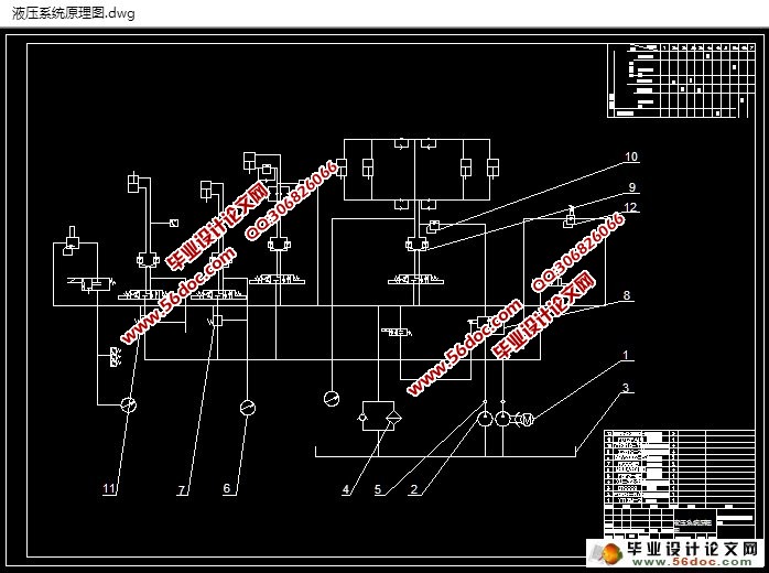
此次设计说明书根据具体参数的计算和工况的分析,从而制定了总体的控制方案。经过各种方案对比以后,制定了液压控制原理图。液压系统选用插装阀集成控制系统,密封性好、通流能力强、压力损失小等是插装阀集成控制系统所具有的特点。根据检测液压系统压力的损失和温升,压力和顺序循环的动作要求本文的设计都能够满足。塑性材料的锻压、冷挤、冲压、弯曲、校直等成型的加工工艺都能够实现。
关键字: 液压系统;挤出机;液压机
Abstract
With increasing numbers of applications of Hydraulic technology in modern technologies, more people want to learn this technology. It is of great significance to correctly design and use hydraulic system, and improve the efficiency and performance of all sorts of Hydraulic equipment.
Extruder is a device that transfers energy based on the Pascal principle via working fluids.Hydraulic press usually consists of a host computer, power system,and Hydraulic control system, the last part of which includes Main cylinder motion and Ejection cylinder movement.
This research devises an overall control method through parameter calculation and working condition analysis. After comparison between various results, we drafted the schematic of the Hydraulic system. A hydraulic system selects Integrated control system for cartridge valve, which poses a number of properties, such as good sealing property,ability to flow,pressure loss is small. Through pressure loss check and the temperature rise check of the hydraulic system, the hydraulic system design of this work can satisfies the requirements for pressure and sequential cycles, and enables practical manufacturing processes for the forging and pressing、stamping、cold extrusion、straightening、bend of plastic material。
Key words:Hydraulic system;Extruder;Hydraulic press
本次设计主要对合模、启模两个过程进行详细分析。
合模过程:机头合上→上、下口型锁紧缸锁紧→楔形变加紧→开始工作
启模过程:楔形变松开→上、下口型锁紧缸松开→机头张开→检修清理
目 录
引言 1
第一章 拟定液压系统原理图 2
1.1 塑料中空成型工艺流程分析 2
1.2 整体液压控制系统原理图 2
1.3 控制系统分析 2
1.3.1 上下机头开合系统 4
1.3.2口型盒上下夹持 5
1.3.3 楔形边锁紧缸 6
第二章 液压缸的计算依据 10
2.1 液压缸的分类 10
2.2 主要参数及常用计算公式 10
2.2.1 压力 10
2.2.2 主要尺寸及面积比 10
2.2.3 液压缸活塞的理论推理和拉力 12
2.2.4 效率 13
2.2.5 液压缸负载率 14
2.2.6 活塞瞬间线速度 15
2.2.7 活塞作用力F 16
2.2.8 活塞加速度a 17
2.2.9 活塞加(减)速时间ta(td) 17
2.2.10 活塞加(减)速行程Sa(Sd) 17
2.2.11 液压缸流量 18
2.2.12 液压缸功率P 18
第三章液压缸的典型结构 19
3.1 端盖与缸筒连接方式 19
3.1.1 拉杆型液压缸 19
3.1.2 螺纹盖型液压缸 19
3.1.3 法兰型液压缸 20
3.1.4 安装方式 20
3.2 专用液压缸典型结构 21
3.2.1 特殊结构液压缸 21
3.2.2 电液伺服液压缸 23
3.2.3 特殊工质液压缸 24
3.2.4 组合液压缸 24
3.2.5 多级液压缸 24
第四章 液压缸主要零部件设计 26
4.1 活塞件的设计计算 26
4.1.1 活塞结构型式 26
4.1.2 密封件沟槽尺寸,公差及粗糙度 26
4.1.3 材料 26
4.1.4 活塞尺寸及公差 26
4.2 活塞杆的设计计算 26
4.2.1 结构 27
4.2.2 活塞杆直径计算 28
4.3 缓冲机构设计计算 31
4.3.1 一般技术要求 31
4.3.2 结构型式 31
4.3.3 缓冲计算 33
4.3.4 调整缓冲机构尺寸 35
结 论 37
参考文献 38
致 谢 39
|


