100T液压机液压执行机构系统设计(含CAD系统原理图)(文献综述,论文说明书12000字,CAD图纸3张)
摘要
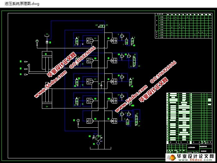
对四柱型液压机的设计,四柱液压机主机由梁,柱,表,动梁,主缸,顶出缸,如主机设计最大工作负荷为1000000牛。通过液压缸的负载变化情况分析,制定液压系统原理图,对电磁铁的工作。主液压缸的设计,主要的尺寸和流量计算,主缸的交换控制行程开关、安全极限速度的旅行。根据技术要求和液压泵的设计计算选择液压元件,如GE系列电磁阀。通过液压系统压力损失和温升计算,液压系统的设计可以满足液压顺序循环的要求,四柱液压机的设计可以实现塑性材料的锻造,冲压,冷挤压,矫直,弯曲成形工艺。用于液压系统的PLC控制系统,通过泵和油缸及各种液压阀实现能量的转换,调节和输送,完成各种工艺动作的循环。
水工结构紧凑,可靠的灵敏度和动作速度,能耗小,噪音低,压力和行程可在规定的范围内调整,操作简单。
关键词:四柱液压机;液压系统;PLC
Abstract
To the design of the four-column hydraulic press, four-column hydraulic press is mainly composed of host, beam, column, table, moving beam, master cylinder, from the top of the cylinder. The mainframe design maximum working load of the 1000 kn. Conditions of the hydraulic cylinder hydraulic cylinder load analysis to determine the change of the hydraulic system development plan of action and the electromagnet work in order. And the size of the main hydraulic cylinder design and calculation of main cylinder and the access and security the flow rate of the master cylinder stroke limit switch through the stroke control. Calculated according to the technical requirement and the choice of the design of the hydraulic pump electromagnetic valve other gm series hydraulic components. Hydraulic system pressure loss and temperature rise, the design of the hydraulic system can satisfy the demands of action sequence cycle hydraulic, four-column hydraulic press is developed plastic material, forging, stamping, cold room ion, straightening, bending and forming process. PLC control system, through a variety of hydraulic pump, hydraulic cylinder and valve to realize the energy conversion, the hydraulic system, regulating and allocation, finish all kinds of craft operating cycle.
A sensitive and reliable hydraulic machine structure is compact, the movement speed, energy consumption, low noise, pressure and stroke can be adjusted within the prescribed scope, the operation is simple.
Keywords: Four-column hydraulic press; hydraulic system; PLC
目录
第一章 绪论 1
1.1 概述 1
1.2 发展概况 2
第二章 液压系统工况分析 3
2.1 载荷的组成和计算 3
2.1.1 主液压缸载荷的组成与计算 3
2.1.2 绘制负载图和速度图 4
2.1.3 初选系统工作压力 5
2.2 液压系统及元件的设计 5
2.2.1 拟定液压系统图 5
2.2.2 电磁铁动作顺序 7
第三章 液压缸的设计 9
3.1 液压缸基本结构设计 9
3.1.1 液压缸的类型 9
3.1.2 缸口部分结构 9
3.1.3 缸底结构 9
3.2 缸体结构设计 9
3.2.1 液压缸主要参数的确定 9
3.2.2 液压缸动作时的流量 11
3.2.3 缸的设计计算 11
3.2.4 活塞的设计 14
3.2.5 活塞杆的设计 16
3.2.6 导向环的设计 18
3.2.7 导向套的设计 18
3.2.8 缸盖的设计 20
第四章 液压元件的选择及性能验算 22
4.1 液压元件的选择 22
4.1.1 液压泵的选择 22
4.1.2 GE系列阀简介及选择 23
4.1.3 辅助元件的选择 24
4.1.4 管件的选择及计算 25
4.1.5 油箱容量的确定 26
4.2液压系统性能验算 26
4.2.1 液压系统压力损失 27
4.2.2 液压系统的发热温升计算 28
第五章 液压系统的PLC控制设计 30
5.1 PLC概述 30
5.2 控制部分设计 30
结论 35
参考文献
致谢
|


