捷达汽车曲柄连杆机构的设计(含CAD零件图装配图)
来源:56doc.com 资料编号:5D19040 资料等级:★★★★★ %E8%B5%84%E6%96%99%E7%BC%96%E5%8F%B7%EF%BC%9A5D19040
资料以网页介绍的为准,下载后不会有水印.资料仅供学习参考之用. 密 保 惠 帮助
资料介绍
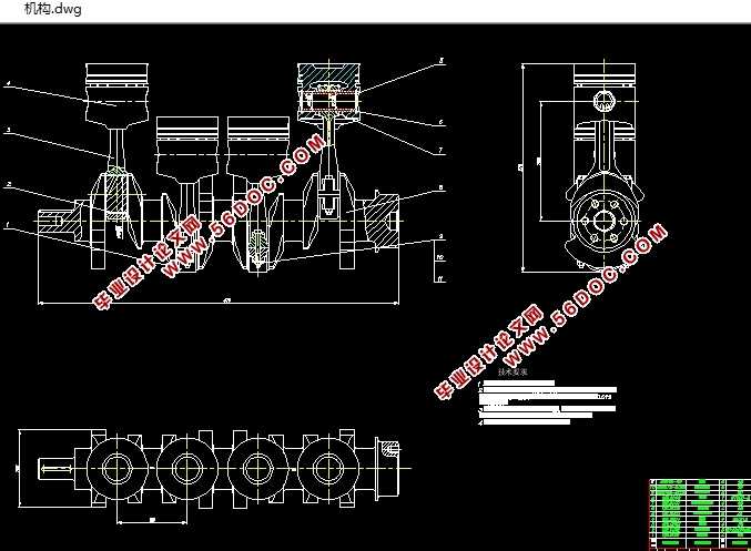
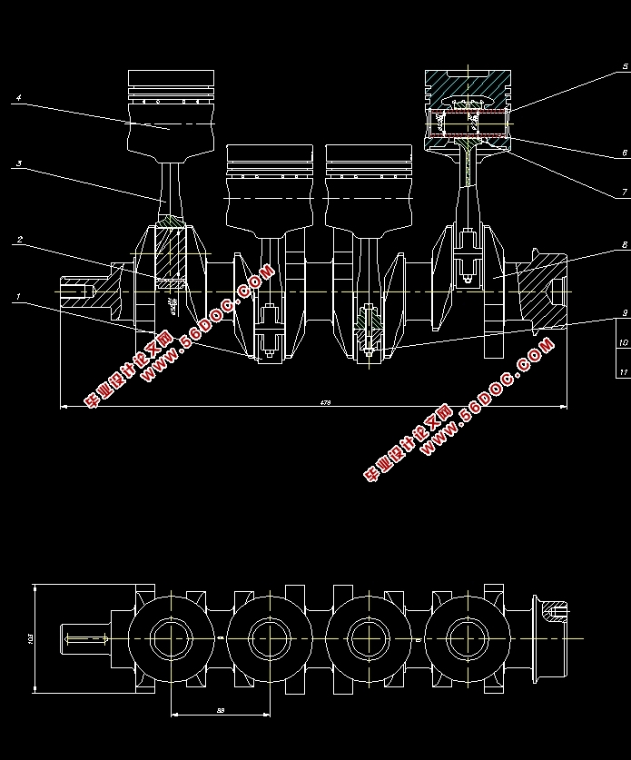
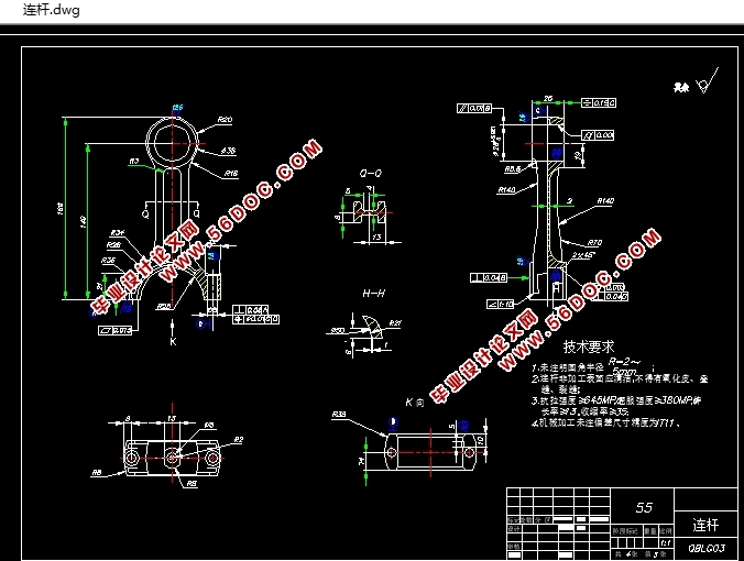
捷达汽车曲柄连杆机构的设计(含CAD零件图装配图)(论文说明书30000字,CAD图纸4张)
摘 要
本文以捷达EA113汽油机的相关参数作为参考,对四缸汽油机的曲柄连杆机构的主要零部件进行了结构设计计算,并对曲柄连杆机构进行了有关运动学和动力学的理论分析与计算机仿真分析。
首先,以运动学和动力学的理论知识为依据,对曲柄连杆机构的运动规律以及在运动中的受力等问题进行详尽的分析,并得到了精确的分析结果。其次分别对活塞组、连杆组以及曲轴进行详细的结构设计,并进行了结构强度和刚度的校核。再次,应用三维CAD软件:Pro/Engineer建立了曲柄连杆机构各零部件的几何模型,在此工作的基础上,利用Pro/E软件的装配功能,将曲柄连杆机构的各组成零件装配成活塞组件、连杆组件和曲轴组件,然后利用Pro/E软件的机构分析模块(Pro/Mechanism),建立曲柄连杆机构的多刚体动力学模型,进行运动学分析和动力学分析模拟,研究了在不考虑外力作用并使曲轴保持匀速转动的情况下,活塞和连杆的运动规律以及曲柄连杆机构的运动包络。仿真结果的分析表明,仿真结果与发动机的实际工作状况基本一致,文章介绍的仿真方法为曲柄连杆机构的选型、优化设计提供了一种新思路。
关键词:发动机;曲柄连杆机构;受力分析;仿真建模;运动分析;Pro/E
ABSTRACT
This article refers to by the Jeeta EA113 gasoline engine’s related parameter achievement, it has carried on the structural design compution for main parts of the crank link mechanism in the gasoline engine with four cylinders, and has carried on theoretical analysis and simulation analysis in computer in kinematics and dynamics for the crank link mechanism.
First, motion laws and stress in movement about the crank link mechanism are analyzed in detail and the precise analysis results are obtained. Next separately to the piston group, the linkage as well as the crank carries on the detailed structural design, and has carried on the structural strength and the rigidity examination. Once more, applys three-dimensional CAD software Pro/Engineer establishing the geometry models of all kinds of parts in the crank link mechanism, then useing the Pro/E software assembling function assembles the components of crank link into the piston module, the connecting rod module and the crank module, then using Pro/E software mechanism analysis module (Pro/Mechanism), establishes the multi-rigid dynamics model of the crank link, and carries on the kinematics analysis and the dynamics analysis simulation, and it studies the piston and the connecting rod movement rule as well as crank link motion gear movement envelopment. The analysis of simulation results shows that those simulation results are meet to true working state of engine. It also shows that the simulation method introduced here can offer a new efficient and convenient way for the mechanism choosing and optimized design of crank-connecting rod mechanism in engine.
Key words: Engine;Crankshaft-Connecting Rod Mechanism;Analysis of Force;Modeling
of Simulation;Movement Analysis;Pro/E

目 录
摘要 I
Abstract II
第1章 绪论 1
1.1 选题的目的和意义 1
1.2 国内外的研究现状 1
1.3 设计研究的主要内容 3
第2章 曲柄连杆机构受力分析 4
2.1 曲柄连杆机构的类型及方案选择 4
2.2 曲柄连杆机构运动学 4
2.1.1 活塞位移 5
2.1.2 活塞的速度 6
2.1.3 活塞的加速度 6
2.2 曲柄连杆机构中的作用力 7
2.2.1 气缸内工质的作用力 7
2.2.2 机构的惯性力 7
2.3 本章小结 14
第3章 活塞组的设计 15
3.1 活塞的设计 15
3.1.1 活塞的工作条件和设计要求 15
3.1.2 活塞的材料 16
3.1.3 活塞头部的设计 16
3.1.4 活塞裙部的设计 21
3.2 活塞销的设计 23
3.2.1 活塞销的结构、材料 23
3.2.2 活塞销强度和刚度计算 23
3.3 活塞销座 24
3.3.1 活塞销座结构设计 24
3.3.2 验算比压力 24
3.4 活塞环设计及计算 25
3.4.1 活塞环形状及主要尺寸设计 25
3.4.2 活塞环强度校核 25
3.5 本章小结 26
第4章 连杆组的设计 27
4.1 连杆的设计 27
4.1.1 连杆的工作情况、设计要求和材料选用 27
4.1.2 连杆长度的确定 27
4.1.3 连杆小头的结构设计与强度、刚度计算 27
4.1.4 连杆杆身的结构设计与强度计算 30
4.1.5 连杆大头的结构设计与强度、刚度计算 33
4.2 连杆螺栓的设计 35
4.2.1 连杆螺栓的工作负荷与预紧力 35
4.2.2 连杆螺栓的屈服强度校核和疲劳计算 35
4.3 本章小结 36
第5章 曲轴的设计 37
5.1 曲轴的结构型式和材料的选择 37
5.1.1 曲轴的工作条件和设计要求 37
5.1.2 曲轴的结构型式 37
5.1.3 曲轴的材料 37
5.2 曲轴的主要尺寸的确定和结构细节设计 38
5.2.1 曲柄销的直径和长度 38
5.2.2 主轴颈的直径和长度 38
5.2.3 曲柄 39
5.2.4 平衡重 39
5.2.5 油孔的位置和尺寸 40
5.2.6 曲轴两端的结构 40
5.2.7 曲轴的止推 40
5.3 曲轴的疲劳强度校核 41
5.3.1 作用于单元曲拐上的力和力矩 41
5.3.2 名义应力的计算 45
5.4 本章小结 47
第6章 曲柄连杆机构的创建 48
6.1 对Pro/E软件基本功能的介绍 48
6.2 活塞的创建 48
6.2.1 活塞的特点分析 48
6.2.2 活塞的建模思路 48
6.2.3 活塞的建模步骤 49
6.3 连杆的创建 50
6.3.1 连杆的特点分析 50
6.3.2 连杆的建模思路 50
6.3.3 连杆体的建模步骤 51
6.3.4 连杆盖的建模 52
6.4 曲轴的创建 52
6.4.1 曲轴的特点分析 52
6.4.2 曲轴的建模思路 52
6.4.3 曲轴的建模步骤 53
6.5 曲柄连杆机构其它零件的创建 55
6.5.1 活塞销的创建 55
6.5.2 活塞销卡环的创建 55
6.5.3 连杆小头衬套的创建 55
6.5.4 大头轴瓦的创建 55
6.5.5 连杆螺栓的创建 56
6.6 本章小结 56
第7章 曲柄连杆机构运动分析 57
7.1 活塞及连杆的装配 57
7.1.1 组件装配的分析与思路 57
7.1.2 活塞组件装配步骤 57
7.1.3 连杆组件的装配步骤 58
7.2 定义曲轴连杆的连接 59
7.3 定义伺服电动机 60
7.4 建立运动分析 60
7.5 进行干涉检验与视频制作 61
7.6 获取分析结果 62
7.7 对结果的分析 64
7.8 本章小结 64
结论 65
参考文献 66
致谢 67
附录 68
|
