自动抹灰机的设计(含CAD零件图装配图,PROE三维图)(论文说明书10000字,CAD图纸15张,PROE三维图)
摘要
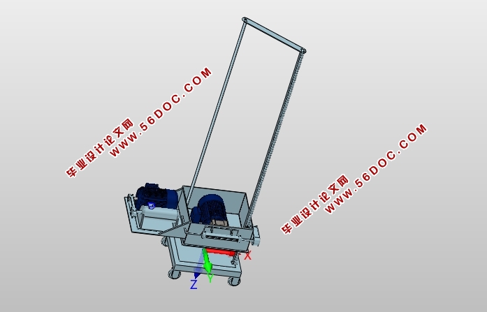
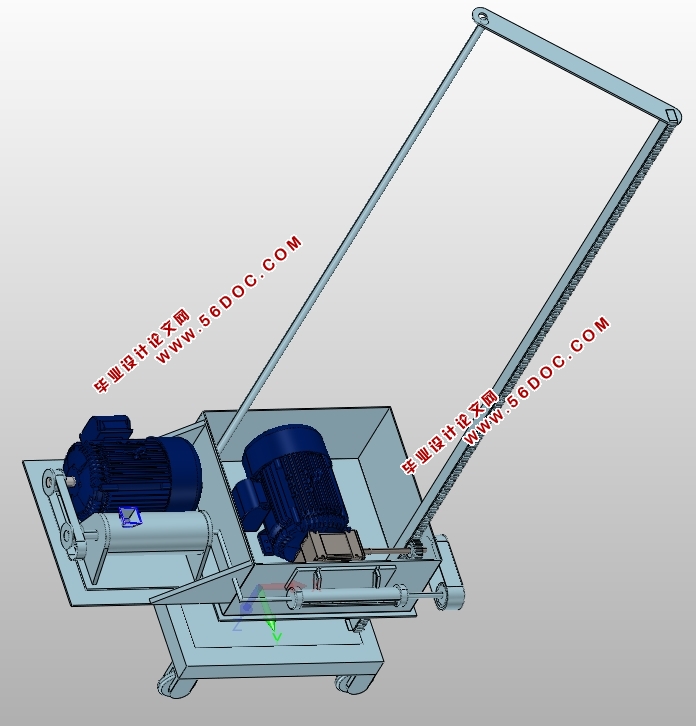
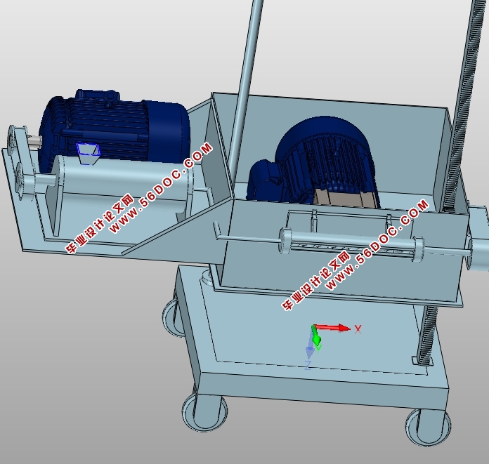
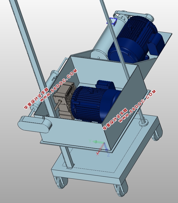
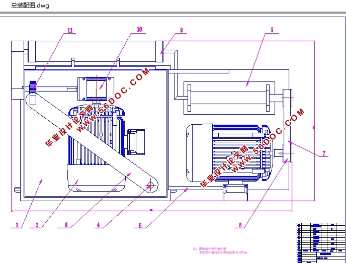
本论文设计的是一种自动抹灰机,文中简要概述了抹灰机目前的发展状况和趋势。对产品进行了方案的确定,按照机械设计的一般步骤,计算并设计了抹灰机上的主要零部件。设计中对工作零件和支架均进行了必要的校核计算。抹灰机的固定导轨纵向固定在装有轮子的基座上,抹灰装置在升降架上,其特点在于:增设活动导轨,活动导轨驱动装置包括固定在平台上的蜗轮减速电机、通过键安装在蜗轮轴端部的齿轮、与齿轮啮合且固定在固定导轨内侧的齿条。升降架与蜗轮蜗杆电机的平台固定连接,并经减震装置与抹灰装置连接。
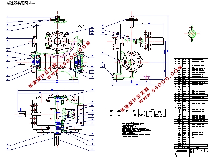
本论文所设计的减速器动力通过齿轮齿条传动,带动活动导轨和抹灰装置上下运动,克服了传统的带轮传动、液压传动等的脉动现象的出现,实现自动抹灰。
关键词:抹灰装置,减速器,升降架,齿轮齿条。
Abstract
This paper designs a kind of automatic pasting machine, this paper briefly summarizes the pasting machine present development status and trends. To the scheme of the products in accordance with the general steps of mechanical design, calculation and design of main components of the plaster machine.To work in the design of parts and support all the necessary checking calculation. Pasting machine fixed guide rail vertical fixed on the base of the wheels, rendering device in lifting frame, its characteristic is: add activity guide rail, guide rail drive including fixed on the platform of worm gear deceleration motor, through the key installation at the end of worm wheel gear and gear meshing and fixed rack and the inside of the fixed guide rail. Lifting platform with worm gear and worm motor fixed connection, and the damping device connected to the rendering device.
In this paper the design of the reducer power through the gear rack driving, drive the activity guide rail and rendering device moves up and down, to overcome the traditional pulley drive, hydraulic drive pulsation phenomenon appeared, such as automatic rendering.
Key words:Plasteringinstallment, Speed reducer, Erector, Wormgear.
总体结构方案
此次设计的抹灰机为自动抹灰机,它是由电动机带动减速器实现减速效果,然后带动齿轮齿条系统使摸灰装置上下运动,以完成抹灰机的工作。为了使结构紧凑,此次设计的减速器为一级蜗轮蜗杆减速器。因为抹灰装置回程时速度远大于工作速度,所以要求选用可调速电动机。
目录
摘要 1
Abstract 2
目录 3
第一章绪论 5
1.1 前言 5
1.2 抹灰机的研究现状与发展趋势 5
1.3 抹灰机的背景 6
1.4 抹灰机的工作特点 6
1.5抹灰机的适用范围 7
第二章总体方案和结构设计 8
2.1 总体结构方案 8
2.2 输料装置 9
2.3 抹灰装置 10
第三章减速器各部件的设计 13
3.1传动比的分配及转速校核 13
3.2减速器各轴转速,功率,转矩的计算 13
3.2.1各轴转速 13
3.2.2各轴的输入功率 14
3.3.3各轴输入转矩 14
3.3蜗轮蜗杆设计 14
3.3.1选择材料 14
3.3.2按齿面接触疲劳强度计算进行设计 14
3.3.3蜗杆与蜗轮的主要参数与几何尺寸确定 16
3.3.4校核齿根弯曲疲劳强度 17
3.3.5求蜗杆圆周速度并校核效率 17
3.3.6计算蜗杆传动主要尺寸 17
3.3.7蜗轮蜗杆的结构设计 18
3.3.8热平衡校核 18
3.4齿轮齿条设计 19
3.4.1选择材料 19
3.4.2按齿面接触强度计算设计 19
3.5蜗杆轴的设计 22
3.5.1扭矩初算轴径 22
3.5.2轴的结构设计 23
3.6输出轴的设计计算 24
3.6.1输出轴上的功率,转速和转矩: 24
3.6.2求作用在蜗杆上的力 24
3.6.3初步确定轴径的最小直径 24
3.6.4轴的结构设计 25
3.6.5精度校核轴的疲劳强度 27
3.7标准件的选择 30
3.7.1滚动轴承的选择 30
3.7.2键连接的选择及校核计算 30
第四章输料器零部件的设计计算 32
4.1底座轴的校核 32
4.2输料电动机的选择 32
4.2.1螺旋轴的功率Pw 32
4.2.2传动装置的总效率η总: 33
4.2.3电机所需的工作功率: 33
4.2.4确定电动机的转速 33
4.2.5确定电动机的型号 34
4.3联轴器选择 34
4.4螺旋轴选择 35
4.4.1 轴的疲劳强度安全系数校核 35
总结与展望 37
参考文献 38
致谢 39
|